
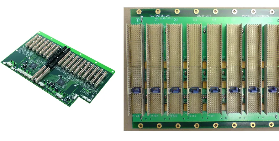
In an era where AI and ML models are growing exponentially, demand for data processing has reached new highs. As the compute core behind this growth, AI servers have pushed internal data rates from PCIe 4.0 at 16 GT/s to PCIe 5.0 at 32 GT/s—and are moving toward PCIe 6.0 at 64 GT/s and even faster protocols such as CXL 3.0. At these speeds, even tiny signal distortions can trigger catastrophic data errors. That’s why AI server motherboard PCB impedance control is no longer optional—it is the foundation that determines whether the entire system succeeds. Accurate impedance control is the lifeline for maintaining SI, reducing BER, and keeping AI servers stable in 24/7 operation.
As interconnect specialists, we know every link from design to fabrication has a deep impact on impedance. A small oversight—material selection, stackup definition, or manufacturing tolerance—can degrade a GPU cluster worth tens of thousands of dollars. This article explains the core challenges and solutions for impedance control on AI server backplane PCBs, how it ties closely to AI server motherboard PCB reliability and cost efficiency, and why early collaboration with an experienced manufacturer like Highleap PCB Factory (HILPCB) is critical.
Why impedance control is the lifeline of AI servers
In high-speed digital design, copper traces on a PCB are not just conductors—they behave like transmission lines. When a digital signal (a high-frequency electromagnetic wave) propagates along a transmission line, it “sees” a characteristic impedance (Characteristic Impedance, Zo). If impedance stays consistent along the path, energy transfers smoothly from transmitter to receiver.
But once the signal encounters impedance discontinuities (trace-width changes, vias, connectors, etc.), part of the energy reflects back (Reflection). Reflections combine with the original signal, causing distortion such as Overshoot, Undershoot, and Ringing. At PCIe 5.0/6.0 Nyquist frequencies in the tens of GHz, these distortions can close the eye diagram and cause sampling errors. BER rises sharply and systems may crash frequently or lose performance. Strict AI server motherboard PCB impedance control is therefore the fundamental guarantee for accurate data transfer between GPU, CPU, and memory.
Key design factors that affect impedance
Characteristic impedance is not an isolated parameter. It is determined by multiple physical and electrical factors. During AI server motherboard PCB layout, engineers must tightly control:
- Trace width and thickness: Wider traces lower impedance; thicker copper also lowers impedance. This is the most direct control knob.
- Dielectric constant (Dk) and dielectric thickness: Lower Dk or thicker dielectric between the signal layer and reference plane increases impedance. AI servers often use ultra-low-loss materials for better signal performance.
- Height above reference plane: The distance from the signal trace to its ground/power reference plane directly affects impedance.
- Differential pair spacing: For differential signals (PCIe, CXL), spacing (S) impacts differential impedance (Zdiff). Smaller spacing increases coupling and reduces Zdiff.
Accurately calculating these interactions is key to achieving target impedance (e.g., 85Ω, 90Ω, 100Ω). Early in the design phase, engineers can use field solvers or online tools such as HILPCB’s impedance calculator for first-pass modeling.
Achieving precise impedance control through stackup design
AI server motherboard PCB stackup is the blueprint for impedance control—it locks the electrical foundation of the PCB during design. A strong stackup must satisfy impedance targets while also supporting PI, EMC, and manufacturing cost.
First, material selection is critical. Traditional FR-4 has higher loss (Df) and poorer Dk stability at high frequency, and often cannot meet AI server requirements. The industry commonly uses high-speed materials such as Megtron 6/7, Tachyon 100G, and Astra MT77. These materials offer lower and more stable Dk/Df over wide bandwidth, reducing attenuation and distortion.
Second, the stackup should be symmetric. Asymmetric stackups create uneven stress during lamination and subsequent thermal shock (e.g., reflow), which can lead to warpage. Warpage changes the distance between traces and reference planes and directly breaks carefully designed impedance. This is essential for long-term AI server motherboard PCB reliability.
Finally, reference-plane integrity is core. High-speed traces need continuous, unbroken ground or power planes for return paths. Any routing across splits breaks the return path, causes sharp impedance changes, and creates severe EMI issues. HILPCB DFM services focus heavily on stackup review to help optimize AI server motherboard PCB stackup for performance and manufacturability.
High-speed PCB material performance comparison
| Material class | Typical material | Dk (@10GHz) | Df (@10GHz) | Typical use cases |
|---|---|---|---|---|
| Standard FR-4 | S1141 | ~4.2 | ~0.020 | Low-speed control signals |
| Mid-loss | Isola FR408HR | ~3.7 | ~0.011 | PCIe Gen3/4 |
| Low-loss | Panasonic Megtron 4 | ~3.4 | ~0.004 | PCIe Gen5, 100G Ethernet |
| Ultra-low-loss | Panasonic Megtron 6/7 | ~3.0-3.2 | ~0.002 | PCIe Gen6, CXL, 400G+ |
What are the core challenges of high-speed differential-pair routing?
Most internal AI server interconnects use differential signaling due to strong common-mode noise immunity. However, differential routing places extremely high requirements on AI server motherboard PCB layout:
- Impedance continuity: Differential pairs must maintain constant differential impedance along the entire path. Any structure that changes width, spacing, or reference distance—BGA escape, via detours, etc.—introduces discontinuities.
- Intra-pair skew: P/N traces must be tightly length-matched. Length mismatch creates phase skew, converts part of the differential energy into common-mode noise, and degrades signal quality. For PCIe 5.0, intra-pair mismatch is often limited to ~1–2 mil.
- Inter-pair coupling and crosstalk: Adjacent differential pairs couple electromagnetically, creating crosstalk. Maintain sufficient spacing (often 3–5× trace width) and use ground shielding where needed.
- Via and connector transitions: The most severe discontinuities often occur at vias and connectors, which introduce parasitic capacitance/inductance. Compensation requires optimized pad/anti-pad design and techniques such as back-drilling.
How via design affects impedance continuity
On AI server motherboards with 20 layers or more, signals inevitably transition between layers through vias. But standard through-holes are one of the biggest SI disruptors.
- Via stub: When a signal transitions from the top layer to an inner layer, the unused portion becomes a “stub”. At high frequency, stubs resonate and can create severe attenuation at certain frequencies. The fix is Back-drilling, which removes the unused copper barrel from the back side to eliminate the stub effect.
- Parasitics: Vias have parasitic capacitance and inductance that lower characteristic impedance. You must optimize via pad and anti-pad sizes. The anti-pad is the clearance opening on reference planes; increasing it appropriately reduces parasitic capacitance.
- HDI: In dense GPU BGA regions, through-holes may not meet routing density. HDI PCB using laser-drilled Microvias and Buried Vias enables higher density without sacrificing SI.
Key points for via optimization
- Prioritize back-drilling: For signals above 28Gbps, back-drilling is often necessary to maintain signal quality.
- Optimize anti-pad size: Use simulation to determine the best anti-pad diameter to match target impedance.
- Add ground vias: Ground vias around signal vias provide good return paths and suppress noise.
- Avoid Via-in-Pad: Unless space is extremely limited and special filling processes are used, avoid drilling vias directly in SMD pads, as it can hurt soldering quality and reliability.
How manufacturing tolerances challenge impedance accuracy
Even with a perfect design, process tolerances shift final impedance. For AI server motherboard PCB impedance control, manufacturing tolerance control is the last mile.
- Etching tolerance: Chemical etching causes small variations in trace width. Advanced manufacturers like HILPCB use micro-etch control and AOI to keep line-width tolerance within ±5% or better.
- Lamination tolerance: During lamination, prepreg thickness has tolerance. This changes dielectric thickness and shifts impedance. High-quality raw materials and precise press control are key.
- Dielectric constant consistency: Even within the same lot or panel, Dk can vary slightly. Strict incoming inspection and lot control are required.
To validate the build, TDR measurement is essential. By measuring impedance coupons on the production panel, you can verify whether traces meet the target (e.g., 100Ω ± 7%). This is especially important for AI server motherboard PCB low volume prototypes—issues can be caught and corrected before ramping into mass production.
How to balance performance and manufacturing cost
Chasing maximum performance usually increases cost. AI server motherboard PCB cost optimization means reducing total cost without sacrificing key performance by making smart design and manufacturing choices.
- Material tradeoffs: Not every net needs the most expensive ultra-low-loss material. A Hybrid Stackup can use high-performance material only on the highest-speed layers, while using lower-cost material for power or low-speed layers.
- Process tradeoffs: Back-drilling, blind/buried vias, and ultra-fine line/space increase cost. Deep DFM collaboration can identify alternatives—for example, optimizing AI server motherboard PCB layout to reduce layer transitions may avoid expensive blind/buried vias.
- Early supplier collaboration: Engaging a manufacturer like HILPCB early provides insight into material cost, process capability, and yield. This helps avoid expensive rework and enables true AI server motherboard PCB cost optimization.
HILPCB high-speed backplane PCB manufacturing capability
| Item | Capability | Value for AI servers |
|---|---|---|
| Max layer count | 64 layers | Supports complex high-density routing |
| Impedance control accuracy | ±5% | Ensures PCIe 5.0/6.0 signal integrity |
| Back-drill depth control | ±0.05mm | Minimizes via stubs and reduces reflections |
| Supported materials | Megtron 6/7, Rogers, Tachyon, etc. | Meets different speed and cost requirements |
Test and validation strategies for long-term reliability
For AI servers deployed in data centers and running 7x24, AI server motherboard PCB reliability is the top priority. Meeting performance at shipment is not enough—boards must remain stable under environmental stresses.
- Comprehensive electrical tests: Beyond TDR impedance, use VNA for S-parameter measurement to evaluate Insertion Loss, Return Loss, and other key metrics.
- Environmental reliability tests: Thermal cycling (power on/off), high-temp/high-humidity, mechanical shock and vibration (shipping/installation). These expose latent defects such as delamination and via cracking.
- One-stop manufacturing and assembly: Choosing a supplier like HILPCB that provides backplane PCB fabrication and SMT assembly helps maintain consistent quality control across the chain. Post-assembly X-Ray verifies BGA soldering, and FCT validates final PCBA function.
Common Questions
Why is impedance control more than just hitting a target ohm value?
Meeting a nominal impedance number on paper is only one part of the job. Real AI server channels also depend on material loss, via transitions, return-path continuity, and fabrication tolerance, so the full interconnect has to be managed as a system.
What should teams validate on the first build before scaling production?
The first build should confirm coupon TDR results, insertion-loss behavior, via performance, and the stability of the chosen stackup in actual fabrication. That data shows whether the design margin is real or whether the layout and process window still need adjustment.
How can you balance impedance performance and manufacturing cost?
The practical approach is to protect the most critical high-speed nets first, then simplify less sensitive layers, materials, and via structures where possible. Early supplier collaboration helps you avoid paying for complexity that does not create measurable signal-integrity value.
Conclusion
AI server motherboard PCB impedance control is a complex system engineering discipline that runs through every stage from concept to mass production. It is not just “drawing traces”—it requires a combined understanding of materials science, electromagnetic theory, high-speed digital design, and precision manufacturing. As AI systems evolve toward higher compute and higher bandwidth, impedance-control requirements will only become more demanding.
In a field full of both challenges and opportunity, choosing a capable, experienced manufacturing partner with smooth communication is key to success. With deep experience in high-speed, high-layer-count PCBs and strong understanding of AI server applications, HILPCB can support customers from AI server motherboard PCB low volume prototypes to large-scale production—helping your design deliver its best real-world performance and win in the market.