
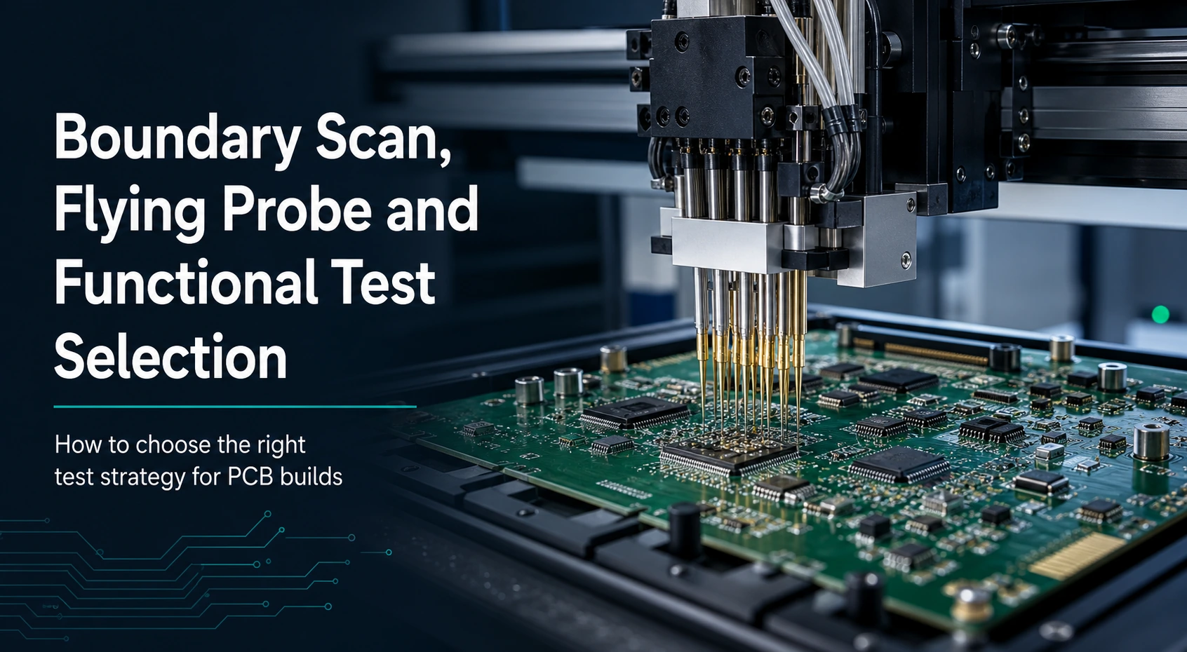
- Treat method choice as an electrical-access decision first. The board should decide what the next build needs to prove before it reaches for
boundary scan,flying probe, orFCTlanguage. - Keep
boundary scan / JTAG, flying probe, fixture-basedICT, and powered functional test in separate lanes. They solve different questions and should not be collapsed into one generic test bucket. - Use package completeness as the gating rule. Fabrication files matter, but they are not enough by themselves to choose a test-access route for an assembled board.
- Keep boundary-scan attached to dense digital test access and interconnect planning only. It does not prove high-speed channel quality, RF performance, or overall product readiness.
- Keep flying probe and
FCTinside a release-planning guide, not a cost or capability pitch. This page does not publish coverage percentages, cycle-time math, fixture ROI, lead-time promises, or reliability claims.
A strong electrical-access guide starts with one smaller question: what evidence does the next build actually need? Once that question is visible, boundary scan, flying probe, fixture planning, and powered functional test can each be placed in the right role instead of being used as generic comfort words.
Search demand around boundary scan, flying probe, ICT, and FCT often treats all of those phrases as if they belong to the same article type. They do not. Some questions are really about test access on dense digital assemblies. Some are about fixture-free electrical screening during changing builds. Some are about when a fixture-backed route becomes worth planning. Some are about powered functional confirmation after electrical-access questions have already been answered. This guide becomes useful only when it reduces that noise to a smaller board-level decision.
That decision is not "which test is best?" It is "which method family answers the next build question without overpromising what it proves?"
This matters because test-method language drifts very easily. A weak draft uses more acronyms to sound more complete. A stronger draft narrows each acronym until the reader can see its job. Boundary scan helps when digital access is constrained and the board still needs structured interconnect-oriented test access. Flying probe helps when the board needs fixture-free electrical checks and the design or program stage does not yet justify dedicated fixture planning. ICT matters as the fixture-based comparison frame behind that selection, even when it is not the headline method for the current build. FCT matters when powered behavior under a defined setup is the relevant downstream question. None of those methods becomes more useful by being described as universal proof.
The safest way to organize the page is around release ownership. Before the board reaches launch, the package should already know:
- what type of electrical evidence the next build needs
- what package inputs are available to support that method
- whether the board is still changing or has stabilized enough for deeper fixture planning
- whether hidden access constraints or dense digital structures make boundary-scan language relevant
- whether the next build needs defect-oriented electrical access or powered-behavior confirmation
Once those answers are visible, method choice becomes much clearer. Without them, the article turns into exactly what it should avoid: a broad glossary that names several methods but does not help the reader decide anything.
In This Guide
- What Does This Selection Guide Actually Decide?
- How Should Boundary Scan, Flying Probe, ICT, and FCT Be Placed in Separate Evidence Lanes?
- What Package Inputs and Access Conditions Should Drive the Test Method Choice?
- How Do You Hand Off the Next Build Without Turning One Method Into Broad Proof?
- What Should Be Included in a PCBA Test Selection RFQ Checklist?
- FAQ
- Next Steps
What Does This Selection Guide Actually Decide?
For a PCBA release review, the practical question is narrower than the full inspection and test toolbox: before an assembled board enters the next build stage, which electrical-access method family matches the evidence the team actually needs?
That sounds obvious, but method names quickly blur the decision. Boundary scan, flying probe, fixture-backed ICT, and powered FCT all sit near test and validation. But they do not all answer the same question, and a useful guide needs to be stricter than a list of method names.
The most useful first step is to rule out four overbroad interpretations.
It is not publishing a universal test glossary. A glossary tells the reader that multiple methods exist. That is too shallow for a release decision.
It is not publishing a broad quality-system article. Inspection, electrical access, release gates, and hidden-joint review are related, but they should not be collapsed into one answer.
It is not publishing a fixture economics guide. The available sources support fixture-free versus fixture-based posture, but not cost math, payback models, or volume thresholds as public claims.
It is not publishing a signal-integrity claim. Boundary scan belongs in the digital test-access layer and does not prove high-speed channel quality, BER, jitter, eye opening, or protocol compliance.
Once those broad, unsafe angles are removed, the release question becomes specific:
The board is approaching assembly release. The team needs to decide whether the next evidence layer is digital test access, fixture-free electrical screening, fixture-backed electrical access planning, or powered functional confirmation. Which route best matches the board's current stage and package?
That is a real engineering question because different methods depend on different package conditions.
Boundary scan depends on design-for-test intent. It belongs in the board when dense digital assemblies, limited physical access, or device-level access planning make structured digital interconnect checking relevant. It is a planning and access question before it is anything else.
Flying probe depends on accessible electrical points, board stage, and the absence of dedicated fixture commitment. It is strongest when the project still needs electrical screening but the design or program stage does not justify treating fixture-backed ICT as the primary route yet.
ICT matters here even though it is not the lead method in the title. Why? Because flying probe is only meaningful as a choice when the article helps the reader understand the comparison frame. Flying probe is the fixture-free posture; ICT is the fixture-based posture. The page does not need to become an ICT tutorial, but it does need that contrast to keep method selection honest.
FCT belongs in a later but related validation layer. It is not mainly about electrical access to nodes, nets, or interconnect structures. It is about powered behavior under a defined setup. That means FCT can appear in the article, but only as a distinct validation layer with distinct ownership. If the draft turns FCT into the final answer to every electrical question, it has already lost the boundary.
This page therefore decides four smaller things:
- What kind of evidence does the next build need first?
- Which method family is designed to answer that question?
- What package completeness is required before that method can be chosen responsibly?
- What does the chosen method still not prove?
Those four decisions make the article more useful than a long list of definitions because they turn old search demand into a release workflow.
Decision Matrix: Early Test Method Goals
| Method family | Safe planning role | What it is best used to clarify | What it should not be used to prove |
|---|---|---|---|
Boundary scan / JTAG |
Digital test access and interconnect-planning layer on dense digital assemblies | Whether the design exposes structured device/interconnect access where direct probing is constrained | High-speed signal integrity, RF channel quality, protocol compliance, or full product readiness |
| Flying probe | Fixture-free electrical screening posture | Whether the current build needs opens/shorts/value/polarity style checks without dedicated fixture commitment | Universal cost advantage, exact coverage, reliability proof, or production readiness by itself |
ICT fixture planning |
Fixture-based comparison posture behind method selection | Whether a more stable program should invest in deliberate node-access planning | Guaranteed higher value for every project, universal fixture ROI, or complete test authority by itself |
FCT |
Powered-behavior confirmation layer | Whether the assembled board behaves as expected under a defined powered setup | Node-level fault localization, interconnect sufficiency, or broad qualification proof |
This table is the center of gravity for the whole guide. Once the board knows which of these lanes it is actually in, the rest of the guide becomes much easier to apply.
One more point matters early: all four methods depend on release context. None of them is meaningful as a raw keyword. The right method is determined by board stage, package visibility, access constraints, and the next evidence question.
How Should Boundary Scan, Flying Probe, ICT, and FCT Be Placed in Separate Evidence Lanes?
The single biggest source of confusion in this topic family is method collapse. A release discussion may use several method names, but the reader still needs to know where one method stops and another begins. Method selection becomes safer and more useful when each method is attached to one primary evidence role instead of being treated as a generic proof word.
The first method family is boundary scan, often called JTAG. A conservative posture is the right one here: boundary scan belongs to the design-for-test and electrical-validation toolkit for dense digital assemblies, especially where direct physical access is constrained. That is a precise and useful statement. It does not need to promise more.
Boundary scan is therefore strongest when the release question is about structured digital access:
- can the assembled design expose interconnect-oriented digital test access cleanly
- does the device mix and intended chain behavior support using boundary-scan language at all
- is the board dense enough that direct physical probing is not the whole answer
- does the release package already understand boundary-scan intent rather than merely naming it
That is why boundary scan should be described as an access layer rather than a performance layer. Once the draft starts implying that JTAG pass or boundary-scan presence proves high-speed link quality, protocol behavior, or complete board readiness, the article crosses a line it should not cross.
The second method family is flying probe. Flying probe is useful because it is fixture-free, but "fixture-free" is not the whole point. The more useful planning statement is that flying probe fits boards that still need electrical screening while the design is changing, the build volume is lower, or a dedicated fixture-backed route is not yet the right near-term commitment.
That framing matters because many weak articles treat flying probe as simply the cheaper or slower cousin of ICT. That is not a useful public claim. The better selection posture is narrower: flying probe belongs where fixture-free electrical verification is the right fit for the current program stage.
That posture keeps the article grounded in real release questions:
- is the design still changing enough that fixture commitment would be premature
- are the accessible electrical points sufficient for useful screening in the current build
- is the immediate goal defect-oriented electrical checking rather than powered behavior
- is the board still in an NPI-like, pilot-like, or limited-volume phase where flexibility matters more than formal fixture planning
This is exactly where dense BGA boards create false confidence. A team strips out physical test points to save area on a double-sided, high-density assembly, then assumes the factory can simply "use flying probe" after build. That request ignores the physical limit of the method. Flying probe cannot reach hidden BGA joints or inner nets that were never exposed for access. If the layout never brought those dark nets into a usable boundary-scan chain or another deliberate DFT structure, the core interconnect can become electrically untestable after assembly. Then an expensive board with a bridge under a BGA may pass the available flying-probe checks, only to fail later during powered functional test after far more cost has already been committed. That is why test-method choice cannot wait until the board is built. Electrical-access planning has to be frozen while layout still controls what can and cannot be reached.
The third method family is ICT, but again only in comparison posture. It only needs enough ICT language to preserve the decision frame around flying probe. The useful point is that flying probe is not meaningful in isolation. It becomes more intelligible when the reader understands that ICT is the fixture-based route and flying probe is the fixture-free route.
That comparison is useful precisely because it should stay bounded. The article can safely say that ICT belongs to fixture-based node-level electrical verification planning for more stable production programs. It should not say how much more coverage that guarantees, how quickly it pays back, or what the exact fixture economics look like.
The fourth method family is FCT. This category must remain separate because it answers a different question. FCT is about powered behavior under a defined setup. It can matter a great deal to the program, but it is not the same as deciding how electrical access will be achieved for screening or interconnect-oriented checking.
That means FCT enters the article as a downstream or adjacent method family:
- it becomes relevant when the next build needs powered-behavior confirmation rather than only access-oriented electrical screening
- it depends on defined behavior expectations, interfaces, and pass/fail logic
- it should not be used as if it eliminates the need for access planning, defect screening, or package completeness
The easiest way to keep the page publishable is to ask one question every time a method name appears:
Is this method being used to explain its own role, or is it being used to borrow authority from another method?
Boundary scan should not borrow high-speed proof authority. Flying probe should not borrow reliability authority. ICT should not borrow economics authority. FCT should not borrow node-access authority. If each term stays inside its own role, the article remains both useful and defensible.
This separation also keeps industry or system words in the right place. Automotive, ADAS, EV power, and AI-chip contexts can change the pressure around the release question, but they should not drag the article into sector-specific performance or qualification claims. The board-level question is still the same: what kind of access or behavior evidence does this build need next?
- Boundary scan belongs to digital test access, not signal-integrity proof.
- Flying probe belongs to fixture-free electrical screening posture, not broad reliability language.
- `FCT` belongs to powered behavior, not access sufficiency.
- `ICT` belongs in the comparison frame behind fixture planning, not in ROI math.
The article does not need to repeat these warnings mechanically. It only needs to organize the page so that each method always appears next to the evidence role it truly owns.
What Package Inputs and Access Conditions Should Drive the Test Method Choice?
Once the evidence lanes are separated, the next decision becomes much more practical: what does the release package need to reveal before a responsible method choice can be made?
This is where many test-method discussions fail silently. They assume that method selection happens after the board is already in production review. In practice, method choice depends on more than fabrication outputs alone, so the release package needs to surface the relevant design and manufacturing intent before the board reaches the next build.
The first input is board construction context. Gerbers, drill data, stackup notes, and other fabrication-facing files matter, but they are only the baseline. They establish what the board is, not which assembled-board test-access method should be used.
The second input is component identity and package mix. A board with dense digital devices, hidden-joint package risk, programmable devices, or mixed access models creates different method pressures than a simpler assembly. That does not turn this page into a package-level design guide. It means test selection becomes more credible when the package mix is visible enough to explain why a digital access method, a fixture-free electrical method, or a powered-behavior method is being emphasized.
The third input is physical access. Flying probe and fixture-based planning both depend on what electrical points can actually be reached on the assembled board. Boundary scan depends on intended digital access behavior rather than only physical probe reach. FCT depends on a different access concept again because it is driven by powered setup, interfaces, and expected behavior. The article becomes stronger when it teaches the reader that "access" is not one thing. Different methods require different forms of access.
The fourth input is explicit test objective. This may be the most important part of the whole article. Without a stated objective, method names become decorative. A board should say whether the next build mainly needs:
- interconnect-oriented digital access
- fixture-free electrical screening
- more deliberate fixture-based node access planning
- powered functional behavior under a defined setup
Those are different aims. They can all matter to the same program eventually, but they should not all be assigned to the same build by default.
The fifth input is program stage. The distinction between flying probe and ICT depends partly on whether the build is still changing or stabilizing. The page keeps that distinction qualitative rather than numeric. It is enough to say that program stage changes whether fixture-free flexibility or fixture-backed repeatability is the better fit for the next step.
The sixth input is handoff clarity. If the selected method cannot be explained in terms of the release package, the next build is already carrying hidden assumptions. The useful public move is to teach the reader that method choice should be visible in the release record rather than being rediscovered after the board enters assembly.
That gives the article a practical selection sequence:
- Identify the next evidence question.
- Confirm the board has enough package context to support a real method choice.
- Check what kind of access that method needs.
- Check whether the current program stage fits fixture-free or fixture-backed posture.
- Confirm what the method still will not prove.
Decision Matrix: Test Method Package Input Requirements
| Method | Required Package Inputs for Accurate Quoting and Setup | Missing this means... |
|---|---|---|
| Boundary Scan | BSDL files for JTAG devices, netlist showing JTAG chain routing, clear pull-up/pull-down resistor intent | The test engineer cannot generate vectors or verify the chain is contiguous. |
| Flying Probe | Intelligent CAD data (ODB++ or IPC-2581), XY component placement, clear BOM, test point / node access map | The machine cannot be programmed to safely probe without hitting component bodies. |
| ICT (Fixture) | Same as Flying Probe + expected panelization layout, tooling hole locations, and bottom-side component heights | The fixture maker will drill the bed of nails in the wrong spots, risking physical damage. |
| FCT | Firmware files, detailed step-by-step test procedure, pass/fail threshold limits, required mating cables/connectors | The operator can power on the board but cannot objectively score the board's behavior. |
This sequence is especially valuable when fixture-design language enters the conversation. Those terms often sound more mature than the underlying package really is. A guide can use that language safely only if it converts it into release questions rather than into automatic method escalation. The presence of fixture words in the search demand does not mean the board is ready for fixture-centered planning. It means the board may be approaching a point where fixture questions should be asked deliberately instead of by habit.
The same is true for broad flying-probe language. This guide does not treat the method name as a universal promise. It keeps the useful posture: flying probe belongs where fixture-free electrical screening is the right near-term route, not where the page needs a broad guarantee.
Related product-page routing also becomes clearer when package inputs lead the decision. If the board is already in a broad end-to-end assembly route and needs a cleaner program-level handoff, Turnkey Assembly is the natural path. If the conversation is shifting toward more stable recurring production posture, Large-volume Assembly becomes more relevant. Those links work because the article first clarifies the release burden instead of asking related pages to absorb ambiguity.
How Do You Hand Off the Next Build Without Turning One Method Into Broad Proof?
Once the board chooses a method family, the last job is to hand the next build forward without inflating what that choice proves. This is the part of the article where overclaim risk rises fastest, because the natural temptation is to make every chosen method sound final.
The safer posture is to treat handoff as evidence transfer rather than verdict language.
If the selected method is boundary scan, the handoff should explain that the build is using a digital test-access posture on a dense digital assembly. It should preserve what the design intended to expose through boundary-scan-aware planning. It should not say that successful access implies high-speed channel quality, interface compliance, or total board readiness.
If the selected method is flying probe, the handoff should explain that the build needed fixture-free electrical screening suited to the current stage and package. It should preserve what was screened and why fixture-free access was the right near-term posture. It should not say that flying probe by itself establishes reliability, production qualification, or broad field readiness.
If the selected comparison frame is fixture-backed ICT planning, the handoff should preserve why the board is stabilizing enough to justify more deliberate node-access thinking. It should not turn that planning choice into cost certainty, coverage certainty, or production authority without stronger project-specific evidence.
If the selected method is FCT, the handoff should preserve what powered behavior was intended to be confirmed, under what setup logic, and as part of which broader release flow. It should not imply that powered confirmation replaces electrical-access planning, package completeness, or long-term reliability evaluation.
This distinction matters because different method names create different kinds of false confidence:
- boundary scan can sound like deep digital proof when it is really an access and interconnect method
- flying probe can sound like a complete low-commitment test strategy when it is really a fixture-free screening posture
ICTcan sound like a universal upgrade path when it is really a fixture-based method family that still depends on package and program fitFCTcan sound like the final truth about the product when it is really powered-behavior confirmation under a defined environment
The page closes with a modest release-handoff model. A strong next-build handoff usually carries:
- revision identity
- the chosen evidence role and why it was chosen
- the package assumptions behind that choice
- the records or notes that show what the build was expected to confirm
- unresolved questions that still belong to later validation or later production planning
That is enough to keep the page valuable without overreaching.
It also keeps the article grounded. This guide is not trying to publish one final truth about testing. It is trying to turn a messy method-choice problem into a smaller board-level guide. The guide succeeds when a reader can leave the page knowing which question boundary scan, flying probe, fixture-backed planning, or powered functional test is meant to answer next.
The article fails when the reader leaves thinking one method name is a proxy for quality, reliability, or system performance.
This is why the page ends where it started: with the next build question. If the team can state that question clearly, method selection becomes manageable. If the team cannot state it, no amount of acronym density will save the release package.
What Should Be Included in a PCBA Test Selection RFQ Checklist?
Before requesting a quote for PCBA testing, ensure the data package clearly defines the required method and provides the files necessary to program the test equipment, rather than leaving the coverage scope open to interpretation.
Flying Probe & ICT Data
- Intelligent CAD Data: Provide ODB++ or IPC-2581 files. Standard Gerbers are often insufficient for programming automated probe targets because they lack intelligent netlist and component centroid data.
- Test Point Definition: Specify if dedicated test points have been added, or if the factory is expected to probe component vias, pads, or leads directly.
- Coverage Expectations: Clarify whether the goal is 100% net coverage (often physically impossible on dense boards) or basic opens/shorts detection on accessible nets.
Boundary Scan (JTAG) Data
- BSDL Files: Provide the Boundary Scan Description Language (BSDL) files for all JTAG-compliant devices in the chain.
- Chain Architecture: Include a clear schematic or block diagram showing the routing of the TDI, TDO, TCK, and TMS signals across the board.
Functional Test (FCT) Data
- Test Procedure: Supply a step-by-step document detailing the exact inputs to apply, the expected outputs, and the acceptable tolerance ranges for pass/fail limits.
- Firmware and Tooling: Specify if test firmware needs to be flashed prior to FCT, and list any mating cables, connectors, or specific loads required for the setup.
FAQ
Is boundary scan the same thing as high-speed validation?
No. Boundary scan belongs to the digital test-access and interconnect-planning layer. It can help on dense digital assemblies where direct physical access is constrained, but it does not prove high-speed signal integrity, RF channel quality, BER, jitter, or protocol compliance.
When is flying probe usually the better near-term choice?
Flying probe is strongest when the board needs fixture-free electrical screening and the current design or program stage does not yet justify dedicated fixture-backed planning as the primary route. The useful point is the posture, not an exact volume threshold or cost crossover.
Why does this guide mention ICT if ICT is not the lead method?
Because flying probe is only meaningful as a selection posture when the fixture-based comparison frame is visible. This page uses ICT narrowly to explain that contrast. It does not try to become a full fixture-design or ICT capability page.
Does functional test replace electrical-access planning?
No. FCT answers a different question: powered behavior under a defined setup. It should sit after or beside electrical-access planning, not replace the need to decide how the board will be screened or how digital access will be handled.
Are Gerbers enough to choose between these methods?
Not by themselves. Fabrication files matter, but the method choice also depends on package mix, electrical access, digital test-access intent, powered-behavior goals, and program stage.
Does choosing one of these methods prove product reliability?
No. Boundary scan, flying probe, ICT, and FCT can contribute different types of evidence, but they do not by themselves establish broad reliability proof, qualification status, or full product readiness.
Next Steps
If the current PCBA is already carrying test-coverage risk, or if the team cannot say with confidence whether the JTAG chain is complete and whether flying probe can physically reach the critical nets, this is the point to stop treating test selection as a downstream factory choice. On dense assemblies, coverage gaps usually become expensive only after the board has already consumed assembly and debug time.
Send the full manufacturing data package, preferably ODB++ or IPC-2581 with physical coordinates and net data, plus the BOM, to [email protected], or upload the data through the Quote page. HILPCB's DFT test engineering team will return a test-access review within 24 hours. That review is meant to close the real pre-build risks: physical probe blind spots, boundary-scan chain validity, and the mixed-test strategy that gives the next PCBA build the best chance of exposing defects before they escape into expensive FCT or system-level debug.
Sources
HILPCB: Turnkey Assembly
Supports the route where package completeness, assembly coordination, and test-handoff visibility need to move together at program level.HILPCB: Large-volume Assembly
Supports the adjacent production-stage route once the build posture becomes more stable and recurring.IEEE SA: IEEE 1149.1 overview
Supports the public identity of boundary-scan as a test-access and interconnect-oriented architecture rather than a signal-integrity proof layer.Internal method-boundary sources routed through local
llm_wiki:pcba-flying-probe-vs-ict-selection-posture,pcba-boundary-scan-jtag-positioning,pcba-test-method-input-package-boundary, andboundary-scan-does-not-prove-high-speed-channel-quality
Support the article's guarded distinction between fixture-free flying probe posture, fixture-backed comparison posture, boundary-scan access planning, and explicit non-claims around high-speed proof.