
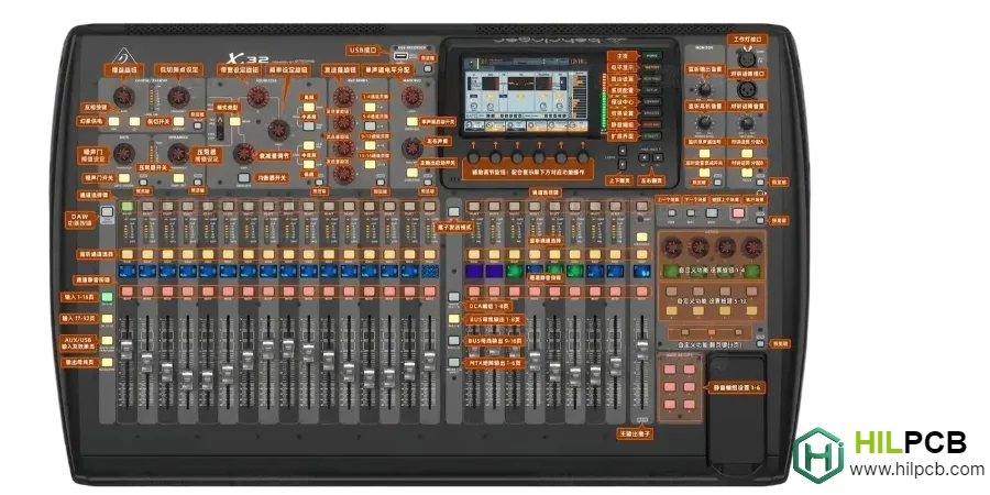
DAW-integrated keyboards provide tactile transport control, motorized mixing capability, and instrument performance from a unified interface. These production controllers combine delicate electronics with robust mechanical components, requiring mixed-technology assembly that maintains quality across both SMT and through-hole processes.
HILPCB provides professional PCB fabrication and PCBA assembly services for DAW controller manufacturers, supporting the unique requirements of motorized fader systems and professional studio equipment.
Menu Navigation
- Transport and Mixing Control Systems
- Motorized Fader System Implementation
- Display and Visual Feedback Integration
- Communication Interface Requirements
- Professional Assembly with Rework Capability
Transport and Mixing Control Systems
Production keyboards include dedicated controls for DAW operation beyond basic note input. These controls see constant use during production sessions, requiring robust PCB construction and reliable component mounting.
Control system reliability depends on proper soldering and component selection for long-term durability.
Control System Elements
- Transport Section: Illuminated play/stop/record buttons with LED integration, jog wheel encoder (100-400 PPR), and marker navigation controls with proper tactile feedback.
- Channel Strip Controls: Per-channel fader, pan encoder, mute/solo/arm buttons with LED indication, organized for intuitive mixing workflow.
- Fader Bank Architecture: 8-fader groups with bank switching logic, requiring consistent fader response across all channels.
- Parameter Control Section: Rotary encoders with push switches for plugin editing, with display feedback integration for parameter names and values.
- Pad Section Integration: Velocity-sensitive pads for drums and clip launching with RGB feedback indicating state and velocity.
- Encoder Implementation: Quadrature decoding with hardware or software handling, acceleration algorithms, and push-switch functionality.
Manufacturing for Control Durability
DAW controllers see heavy daily use requiring robust through-hole soldering for mechanical components. Mixed-technology assembly provides proper solder joints on encoders, faders, buttons, and connectors.
Motorized Fader System Implementation
Touch-sensitive motorized faders track DAW automation and provide tactile mixing control. Motor driver circuits require proper power handling, while touch sensing demands clean capacitive measurement unaffected by motor noise.
Motorized fader PCBs combine power electronics with sensitive analog sensing.
Motorized Fader Elements
- Motor Driver Circuits: H-bridge drivers (DRV8833, TB6612FNG) with proper decoupling, flyback protection, and PWM filtering for quiet operation.
- Position Feedback: Fader potentiometer interface with proper ADC resolution and filtering for accurate position sensing.
- Touch Detection: Capacitive sensing circuits with proper shielding and filtering to distinguish touch from motor-induced noise.
- Servo Control: PID control implementation achieving ±1% position accuracy with smooth motion profiles.
- Power Distribution: Adequate trace width and copper pour for motor current, with proper separation from sensitive signal circuits.
- Thermal Considerations: Motor driver heat dissipation through thermal vias and adequate copper area.
PCB Requirements for Motor Systems
Motorized fader boards require adequate copper weight (2oz recommended) for motor current, proper power/signal separation, and controlled impedance for USB communication.

Display and Visual Feedback Integration
Comprehensive visual feedback enables confident DAW control without constantly watching the computer screen. Display systems range from simple LED indicators to full LCD/OLED scribble strips on each channel.
Display reliability affects daily usability throughout product lifetime.
Display System Elements
- Per-Channel Displays: OLED scribble strips (128×32) showing track name and parameter value with proper contrast and viewing angle.
- Meter Integration: LED bar meters (8-12 segments per channel) with fast peak response for level monitoring.
- LED Button Feedback: Tri-state illumination (off/dim/bright) or RGB LEDs indicating button states and modes through bidirectional DAW communication.
- Encoder Ring Indicators: LED rings around encoders showing parameter position for intuitive adjustment.
- Main Display Options: Character LCD or graphic OLED for global status, with touch integration for premium designs.
- FPC Connections: Flexible printed circuit connections to display modules with proper strain relief and connector reliability.
Manufacturing for Display Systems
Display integration requires precise connector mounting for reliable FPC connections, proper LED placement for uniform illumination, and adequate power distribution for display arrays.
Communication Interface Requirements
DAW controllers use bidirectional communication protocols for deep software integration. USB implementation quality affects reliability, while proper protocol implementation ensures compatibility across DAW applications.
Communication reliability determines professional usability.
Communication Elements
- Mackie Control Protocol: Industry-standard control surface protocol with 8-channel fader emulation, V-Pot encoders, and LCD text display via SysEx messages.
- HUI Protocol Support: Avid/Pro Tools native protocol for professional audio production requiring precise timing and reliable communication.
- USB-MIDI Multi-Port: Multiple virtual MIDI ports organizing keyboard, transport, mixer, and display data for flexible software routing.
- Bidirectional Data Flow: Receiving fader positions, meter levels, and track names from DAW while sending control changes.
- Low-Latency Operation: USB stack implementation ensuring responsive control feel matching dedicated hardware controllers.
- Power Delivery: USB bus power for portable operation or external power for systems with many motorized faders.
USB Implementation Requirements
Control surface USB requires 90Ω differential impedance, proper ESD protection, and reliable connector mounting.
Professional Assembly with Rework Capability
DAW controller prototypes often require modifications during development—motor driver changes, fader substitutions, or touch sensing adjustments. HILPCB provides professional rework capability alongside production assembly.
Why Choose HILPCB for DAW Controller PCB
Integrated Rework Services
When your prototype needs component changes—wrong motor driver, updated touch IC, or modified power stage—our PCB rework services handle corrections in-house. BGA rework, component replacement, and ECO implementation happen without external delays.
Motorized Fader Power Handling
Motor driver sections require adequate copper for current handling. Our FR4 PCB fabrication supports 2oz copper on power layers, preventing voltage drop that causes motor position errors and touch detection interference.
Mixed-Technology Excellence
DAW controllers combine SMT electronics with numerous through-hole components—faders, encoders, switches, connectors. Our selective soldering achieves full barrel fill on through-hole joints while protecting adjacent SMT assemblies.
Touch Sensing Reliability
Capacitive touch circuits are sensitive to contamination and stray capacitance. Clean fabrication and assembly practices ensure your touch sensing performs as designed in the final product.
Display Module Integration
OLED scribble strips and LCD modules require precise FPC connector mounting. Our assembly processes ensure reliable display connections that survive years of studio use.
Studio Equipment Quality Standards
- X-ray inspection for motor driver BGA packages
- AOI verification of SMT placement and soldering
- Functional testing protocols for control surface verification
Development Through Production
- Small batch assembly with rework support for prototype iterations
- Large volume assembly when your design is production-ready
- Turnkey assembly sourcing motorized faders and specialized components
Contact us with your DAW controller project—we'll discuss DFM optimization and rework strategy for efficient development.
Common Questions
What makes a DAW controller PCB different from a standard keyboard board?
DAW controller boards often combine motorized faders, encoders, touch sensing, displays, and dense mixed-technology assembly instead of only scanning key switches. That combination raises the bar for layout discipline, assembly sequencing, rework planning, and functional verification.
Why does rework strategy matter so much during DAW controller development?
Because studio control products usually go through multiple tuning cycles around feel, response, firmware behavior, and feature integration before the design fully settles. Planning for rework early helps teams iterate faster without turning every prototype change into avoidable cost or schedule loss.
What should be validated before a DAW controller reaches production release?
The team should validate mixed-technology assembly robustness, touch and display reliability, motorized or moving-control behavior, and full control-surface functionality instead of checking only basic power-up. Production release is safer when studio-use expectations are reflected in both manufacturing and test coverage.