
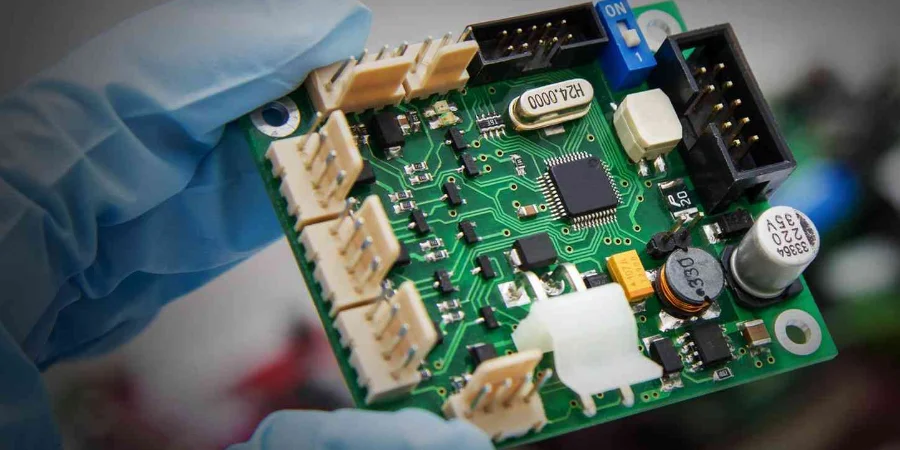
First article inspection (FAI) is a documented comparison of the first representative build with the released product definition and specified acceptance requirements. For power and cooling PCBs, useful FAI evidence connects the exact board configuration to workmanship, dynamic electrical behavior, thermal performance and every recorded deviation; a board that merely powers on is not enough.
Key Takeaways
- Separate FAI from design qualification, pilot-process validation and routine production inspection; each answers a different release question.
- Apply SAE AS9102C only when a customer, contract or aerospace quality system invokes it.
- Trace the BOM, drawings, stackup, assembly data, firmware, approved substitutions, rework and test procedure to the serialised first article.
- Map every characteristic to its method, equipment, result and reaction owner.
- Test hot-swap, inrush, source transfer, protection and telemetry under declared input, load, temperature, firmware and fixture conditions.
- Use thermal images diagnostically, not as standalone proof of compliance.
- Reopen affected characteristics after a design, source, process, tooling, location or lapse-related change; justify any partial FAI.
Table of Contents
- What Does FAI Prove—and What Does It Not Prove?
- FAI vs Qualification, Pilot Validation and Production Control
- Define the Configuration Before Inspecting the Board
- Build a Characteristic Accountability Matrix
- Inspect Power and Cooling Assembly Risks
- Test Dynamic Power Behavior Under Declared Conditions
- Make Thermal Evidence Decision-Ready
- Verify Firmware, Telemetry and Cooling Control
- Control Measurement and Test Evidence
- Handle Nonconformance, Rework and Deviations
- When Is Full or Partial FAI Required?
- Use a Power and Cooling Release Gate
- Avoid Common FAI Failure Modes
- Power and Cooling PCB FAI RFQ Checklist
- Reference Standards and Responsibility Boundaries
- How HILPCB Supports First-Article Builds
- FAQ
- Conclusion
What Does FAI Prove—and What Does It Not Prove?
FAI provides configuration-controlled evidence that a representative build satisfies selected characteristics and acceptance requirements. SAE AS9102C defines a structured aerospace framework when contractually applicable; other customers may use their own first-article record.
The scope must be explicit because “FAI” is often stretched to cover unrelated activities. A complete record can show that the inspected unit matches its released definition and specified tests passed. It does not automatically show that:
- the design is adequate for every operating condition;
- the process is statistically capable or stable;
- environmental, EMC, reliability or life requirements are qualified;
- the product satisfies certification obligations; or
- later units will conform without production controls.
Functional evidence belongs in FAI only when released requirements call for it. Those requirements—not a generic checklist—define electrical, thermal, communication and fault acceptance.
FAI vs Qualification, Pilot Validation and Production Control
These activities can share data but do not substitute for one another.
| Activity | Primary question | Typical evidence | What it does not establish alone |
|---|---|---|---|
| First article inspection | Does this build conform to released characteristics? | Configuration, inspection, functional results and dispositions | Design adequacy, capability or future lots |
| Engineering qualification | Does the design meet performance and environmental requirements? | Corner, stress, environmental and qualification reports | Repeatable production execution |
| Pilot/process validation | Can the intended line repeatedly build acceptable units? | Yield, defect, capability, fixture and route evidence | Performance beyond validated scope |
| Production control | Does each lot remain within controls? | Incoming, inspection, test, sampling and traceability | Qualification or first-article accountability |
The release decision is layered: FAI can pass while qualification remains open, or qualification can pass while the production-representative build has configuration discrepancies.
Define the Configuration Before Inspecting the Board
Inspection starts with identity. If a team cannot reconstruct what was built, a collection of test screenshots is debug material rather than auditable FAI evidence.
Lock these records to the first article:
- PCB/assembly part numbers and revisions, drawings, stackup, BOM and approved parts;
- centroid, stencil, workmanship notes and torque requirements;
- firmware or programmable-logic image, configuration, calibration and checksum;
- substitutions, waivers, concessions and temporary deviations;
- unit, PCB and critical-component serial/lot identifiers; and
- traveler, line, date, route, rework and inspection/test procedure revisions.
An alternate is not equivalent merely because its headline rating matches. A controller, MOSFET, shunt, connector, fan driver or sensor change can alter timing, safe operating area, loss, accuracy, thermal response or firmware behavior. Record authorization and reopen affected characteristics.
Build a Characteristic Accountability Matrix
A closed chain from requirement to reaction prevents dimensions receiving sign-off while power and cooling evidence remains in bench notes.
| Design characteristic | Acceptance source | Method and conditions | Equipment / capability | Result and source record | Reaction owner |
|---|---|---|---|---|---|
| PCB construction/copper | Drawing and stackup | Document, coupon or microsection as required | Approved method | Unit-linked report | Supplier quality |
| Connection resistance | Electrical specification | Four-wire method at stated fixture, temperature and current | Suitable calibrated meter/source | Raw result and limit | Power engineer |
| Hot-swap inrush | Board/system requirement | Defined source, impedance, capacitance, load and firmware | Current probe/shunt and oscilloscope | Waveform and limit | Power engineer |
| Thermal/cooling behavior | Assembly and thermal requirements | Inspection plus specified load and cooling state | Inspection system and sensors | Unit-linked result | Manufacturing/thermal engineer |
| Telemetry/firmware | Interface and release records | Operating points, checksum, alarms and recovery | Controlled programmer and references | Log with error calculation | Firmware/test engineer |
If a requirement lacks a source, limit or owner, resolve it before the build rather than inventing a criterion after seeing data.
Inspect Power and Cooling Assembly Risks
Power and cooling boards concentrate risk in high-current joints and heat-transfer interfaces. Choose inspection according to visibility and failure consequence.
- Use SPI and AOI for relevant paste and visible-joint conditions.
- Use X-ray for thermal-pad, bottom-terminated, BGA or other hidden joints when required, with criteria defined before image review.
- Inspect lugs, busbars, shunts, fuses, high-current connectors, insulation, spacers, heatsink hardware and specified torque controls.
- Confirm polarity, fitted options, creepage/clearance controls and coating or thermal-material keepouts.
- Record hand soldering, jumpers, component replacement, pad repair and cleaning.
AOI and X-ray are complementary. Neither proves resistance, insulation or thermal performance without a released method.
For high-current construction, involve heavy copper PCB review before release. For heat-spreading constraints, align the stackup and assembly plan with high thermal PCB requirements rather than trying to compensate during inspection.
Test Dynamic Power Behavior Under Declared Conditions
Static continuity and nominal power-on miss risk during insertion, startup, source transfer and faults. Exercise the actual functions invoked by the design.
Declare the test envelope for every waveform: input voltage and source limit; source/harness impedance; input and load capacitance; load profile; ambient and initial temperature; cooling/enclosure state; firmware/configuration; and probe location, bandwidth, sample rate and trigger.
Verify applicable inrush, output-ramp, voltage response, current-limit, overload, retry/latch-off, discharge and restart requirements. For redundant or ideal-diode paths, test priority, reverse-current blocking, transfer and fault isolation using defined source offsets and timing.
Do not invent generic ranges. Limits come from the circuit, component operating area, interconnects, source, load and product requirement.
Make Thermal Evidence Decision-Ready
A thermal image maps apparent surface temperature under one condition. Emissivity, reflections, airflow, coating and settings affect readings; buried copper and junction temperature may remain invisible.
A useful thermal record includes unit/revision identity; input, output, load and stabilization time; ambient, airflow, enclosure, heatsink and cooling state; sensor location and calibration; camera settings and emissivity treatment; applicable limits; measured results; and shutdown, derating or recovery behavior.
Use imaging to find hotspots and target contact measurements. Use embedded sensors, junction estimates or correlated measurements for internal-temperature requirements. A cool image can still hide current-sharing, transient or interface problems under an incomplete load.
Verify Firmware, Telemetry and Cooling Control
PMBus identifies revision 1.5 as its current full published specification, but devices may implement documented subsets and vendor behavior. Verify the actual device, firmware and command map.
Where applicable, check addressing and configuration; voltage/current/power/temperature readback; units, scaling and update rate; warnings and status bits; timeout, stale-data, reset and power-cycle behavior; fan/pump command and feedback; fail-safe state; and firmware/calibration traceability.
Telemetry passing at idle does not prove accuracy under load. Compare it with a traceable reference over the required operating range, and distinguish a stale plausible value from valid fresh data.
Control Measurement and Test Evidence
Method fitness matters beyond a calibration sticker. Lead resistance, fixture repeatability, bandwidth, resolution or probe placement can invalidate a calibrated instrument's result.
For each critical result, retain equipment identity, calibration, software/fixture revisions, connections, conditions, raw data and the acceptance calculation. If tolerance is close to method uncertainty or variation, obtain metrology review rather than rounding a marginal result into a pass.
Golden units can detect fixture drift but do not create an absolute limit. Control fixture self-test, maintenance and revision; link manual calculations to the inspected serial number.
Handle Nonconformance, Rework and Deviations
Do not erase a failure by recording only the repaired retest. Preserve the original condition, nonconformance, containment, disposition, rework, reinspection and retest.
Decide separately whether the repaired article conforms, other material needs containment, corrective action is required, and the change triggers full or partial FAI.
Use-as-is, repair, substitution and deviation require the prescribed approval route. Never redefine a criterion to fit observed data.
When Is Full or Partial FAI Required?
When invoked, AS9102C controls; otherwise use customer change rules. Repeat enough FAI to cover every potentially affected characteristic and document the rationale.
| Change or event | Likely affected evidence | FAI planning response |
|---|---|---|
| New part or new design revision | All product and process characteristics | Plan a full FAI unless the controlling requirement authorizes another scope |
| PCB stackup, copper, material or fabricator change | Impedance, insulation, resistance, thermal path, soldering and mechanical fit | Reopen affected fabrication, assembly, electrical and thermal characteristics |
| MOSFET, controller, shunt, connector, fan or sensor substitution | Ratings, startup, loss, accuracy, firmware behavior, thermal and sourcing controls | Engineering review plus partial FAI and qualification tests as affected |
| Stencil, paste, reflow, selective-solder or tooling change | Joint formation, voiding, alignment and workmanship | Reopen relevant process-linked characteristics and inspection evidence |
| Manufacturing location or major line transfer | Equipment, tooling, programming, operators and process route | Re-establish affected first-article and process-validation evidence |
| Firmware or calibration change | Configuration, timing, telemetry, protection and cooling response | Reopen programming and affected functional characteristics |
| Long production lapse or lost process continuity | Tooling, material, personnel, equipment and process state | Apply the customer/quality-system trigger and document restored evidence |
A partial FAI is an engineering and quality decision tied to change impact, not fewer checks for convenience.
Use a Power and Cooling Release Gate
Before pilot release, review one decision table rather than separate inspection, bench and thermal folders.
| Gate | Minimum release evidence | Stop condition |
|---|---|---|
| Configuration | Unit-linked revisions, firmware, substitutions and deviations | Identity or approval trail is incomplete |
| Workmanship | Required inspection and rework closure | High-risk joints lack defined evidence |
| Electrical | Specified startup, load, protection and transfer results | Conditions, limits or disposition are missing |
| Thermal/controls | Declared load/environment, cooling state, firmware and telemetry | Hotspot, scaling or recovery remains unexplained |
| Measurement/quality | Equipment, raw-data linkage and closed nonconformance | Method or disposition cannot support release |
Passing supports controlled release but does not replace qualification or capability work; list open actions separately with owners and gates.
Avoid Common FAI Failure Modes
| Failure mode | Why it escapes | Better control |
|---|---|---|
| Nominal power-on is treated as complete FAI | Transients, load and faults remain untested | Use requirement-linked dynamic cases |
| Screenshots lack configuration context | Evidence is separated from build identity | Record serial, revision and conditions |
| Thermal image is treated as a criterion | Imaging and load limitations are ignored | Correlate to specified methods and limits |
| Alternate is accepted by description | Timing, loss, accuracy or firmware differs | Review impact and reopen characteristics |
| Rework history disappears | The repaired unit becomes an undocumented reference | Preserve failure, repair and retest traceability |
Power and Cooling PCB FAI RFQ Checklist
Released design: drawings, Gerber/ODB++, netlist, stackup, impedance table, BOM/approved parts, centroid, stencil, schematics and mechanical model.
Configuration: part/revision and serialisation rules, firmware/checksums, programming, substitutions, deviations and traceability depth.
Power/thermal: ranges, transient profiles, inrush, source transfer, protection, copper/connector constraints, ambient, airflow, enclosure, heatsinks, interfaces and temperature limits.
Cooling/telemetry: fan or pump loads, command/feedback, stall behavior, protocol map, scaling, alerts, update rate and recovery.
Inspection/tests: workmanship class, CTQs, SPI/AOI/X-ray scope, limits, fixtures, procedure/software, equipment/calibration and raw-data format.
Quality release: FAI template, AS9102C applicability, authorities, nonconformance workflow, FAI triggers, retention and release gate.
For an integrated first build, submit this package with a turnkey PCB assembly request. If the program needs engineering iterations before release, define which evidence must be repeated across small-batch assembly builds.
Reference Standards and Responsibility Boundaries
- SAE AS9102C — SAE International
- IAQG 9102 — International Aerospace Quality Group
- IPC-A-610 — IPC
- J-STD-001 — IPC
- IPC-2221 — IPC
- IPC-6012 — IPC
- ISO 9001 — International Organization for Standardization
- AS9100 — SAE International / International Aerospace Quality Group
The contract, customer drawing, product requirements and quality plan determine applicable editions, classes, forms and acceptance criteria. HILPCB can produce and assemble a PCB to released requirements and provide specified configuration, workmanship and test records. The product owner retains responsibility for design adequacy, system safety, qualification, regulatory or certification compliance, reliability, process-capability decisions and final release.
How HILPCB Supports First-Article Builds
HILPCB can align fabrication, component sourcing, assembly, inspection and specified electrical testing around one controlled build package. The useful starting point is a characteristic list and evidence plan, not a generic request to “do FAI.”
Share the released revision, CTQs, hidden-joint risks, power/thermal conditions, firmware, fixtures, acceptance limits, traceability needs and change triggers. HILPCB can then review manufacturability, inspection access, test coverage and record structure before the build, while unresolved product-level qualification remains visible to the design authority.
FAQ
Is first article inspection the same as design validation?
No. FAI checks a build against released characteristics. Qualification determines whether the product meets performance, environmental, safety and reliability requirements. Results may overlap, but neither replaces the other.
Does every power PCB need an AS9102C FAI?
No. AS9102C is used when invoked by contract, customer or an aerospace quality system. Other products can use customer-defined records without claiming AS9102C compliance.
Should thermal imaging be part of power PCB FAI?
Yes, for hotspot detection when load, ambient, airflow, emissivity and configuration are controlled. It does not prove junction temperature or compliance alone; correlate it with the specified method.
When can a partial FAI be used after a change?
Use it when permitted and a documented impact review identifies every affected characteristic. Repeat those checks, retain the rationale, and add qualification or process validation when needed.
Conclusion
A credible FAI for power and cooling PCBs is a traceable release argument: the right configuration was built, each critical characteristic had a defined method and limit, dynamic and thermal results were captured under declared conditions, and every deviation reached an authorized disposition.
Send HILPCB the released design package, characteristic matrix, test conditions and change-control requirements before the first build. That preparation turns FAI from a folder of inspection images into evidence a quality, engineering and procurement team can actually use.