
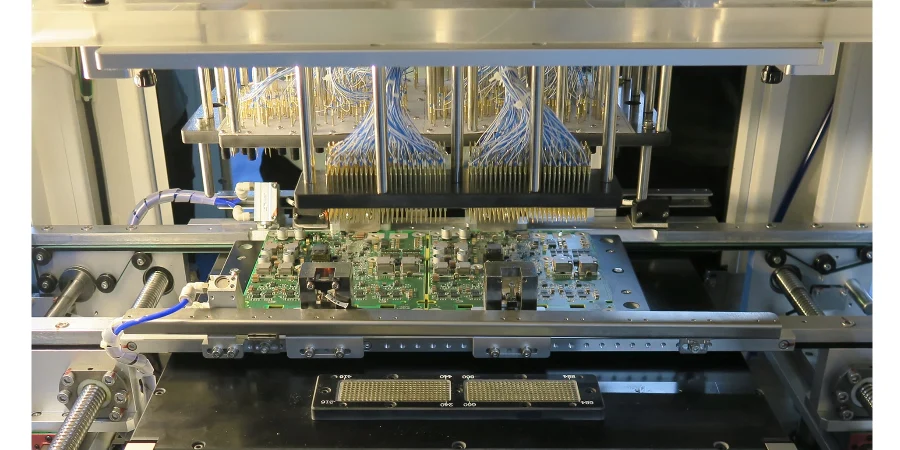
A 5G/6G ICT or FCT fixture is the controlled mechanical, electrical, RF, thermal, and software interface between automated test equipment and a communication PCBA. Its job is not to prove every radio requirement; it must make defined production measurements repeatably enough to separate board defects from fixture variation.
Key Takeaways
- ICT, flying probe, boundary scan, FCT, conducted RF test, and OTA test close different risks. A fixture specification should state what each station proves and misses.
- At mmWave frequencies, the cable, connector, probe, load board, launch, grounding, and clamp position are part of the measurement channel.
- Calibration must place a stated reference plane near the DUT interface. De-embedding is valid only when the extracted fixture model and physical setup remain representative.
- Integrated antennas and phased arrays require OTA validation for radiated behavior. Conducted production screening cannot prove beam pattern, total radiated power, or installed antenna performance.
- A golden unit is a drift monitor, not an absolute truth source. Fixture release also needs known-good/known-bad samples, limit rationale, GR&R or another measurement-system study, and false-fail controls.
- Connector care, specified torque, probe-cycle tracking, cleaning, sacrificial adapters, verification checks, and recalibration triggers belong in the production test plan.
Contents
- What each test method proves
- How to define the production test boundary
- How to control the RF measurement channel
- When conducted test must become OTA
- Mechanical power thermal and shielding design
- Test limits GRR and false-fail control
- EVT to volume-production release gates
- Fixture maintenance and change control
- Common fixture failure modes
- RFQ checklist
What Each Test Method Proves
The first fixture-design decision is not the probe type. It is the allocation of defects and performance risks across stations. Adding more measurements to one fixture can increase cycle time without closing the right blind spots.
| Method | Strong coverage | Important blind spots | Typical role |
|---|---|---|---|
| AOI and X-ray | placement, polarity, solder geometry, hidden-joint evidence | electrical values, firmware, powered function, RF performance | upstream process control |
| Flying probe | opens, shorts, selected component values and accessible nets without dedicated tooling | slow on dense programs; limited powered and RF behavior | prototypes and low-volume structural test |
| Bed-of-nails ICT | fast access to many nets, opens/shorts, analog signatures, selected device checks, programming | inaccessible nets, firmware behavior, antenna performance, complete RF function | volume manufacturing defect detection and diagnosis |
| Boundary scan/JTAG | supported digital interconnects, pin states, memory or programmable-device access | analog/RF paths, non-compliant devices, nets outside the scan chain, system performance | access recovery where physical probing is limited |
| FCT | boot, current profile, interfaces, control paths, firmware interaction, functional outputs under defined stimuli | detailed component fault isolation, latent reliability, untested modes and environments | board-level functional release |
| Conducted RF test | selected transmit, receive, gain, phase, spectrum, EVM, sensitivity, S-parameters, or calibration states | antenna pattern, efficiency, enclosure detuning and radiated interactions | characterization or fast production screening with an RF port |
| OTA test | integrated antenna and radio behavior, beam direction, radiated power/sensitivity, spatial response | every field environment and every operating state | antenna-in-package, phased-array and finished-product validation |
| 3GPP or market conformance | defined regulatory or standards-based cases in an authorized configuration | production workmanship on every unit; untested product modes | formal qualification, not an ICT/FCT substitute |
Boundary scan follows the IEEE 1149 family and is valuable for supported digital access, but it is not high-speed channel validation. Likewise, an FCT pass proves only the functions, limits, firmware, and environmental conditions included in the released program.
How to Define the Production Test Boundary
Production screening and engineering qualification have different economics. Qualification explores margins, modes, temperature, orientation, bandwidth, channels, beam states, and interactions. Production test should use the smallest evidence set that reliably catches expected assembly, programming, calibration, and handling escapes.
Define the boundary with a requirement-to-test map:
- List the product requirements and credible manufacturing defects.
- Assign each item to inspection, ICT, boundary scan, FCT, conducted RF, OTA, environmental test, or formal qualification.
- Record the sample level: every unit, lot sample, first article, periodic audit, or engineering-only.
- State the measurement method, limit source, uncertainty allowance, retest rule, data record, and owner.
- Identify uncovered risks explicitly instead of describing the fixture as “full coverage.”
For a phased-array radio, a production FCT might verify power rails, boot, register access, SPI control, selected gain/phase states, current, temperature telemetry, and a short RF screen. Characterization may sweep every relevant channel and beam state. OTA qualification then checks the integrated array’s radiated behavior. These layers support each other; none should borrow the name or acceptance authority of another.
How to Control the RF Measurement Channel
At RF and mmWave frequencies, the fixture is a network rather than a transparent wire. Its insertion loss, return loss, phase, isolation, leakage, flexure, temperature, and connection repeatability can consume the DUT margin or create false failures.
Put the calibration reference plane in the specification
“Calibrated VNA” is incomplete because it does not state what remains between the calibration plane and the DUT.
| Reference-plane choice | What remains inside the measured result | Suitable use | Required evidence |
|---|---|---|---|
| Instrument ports | cables, adapters, switches, fixture, probes and launches | debug only when fixture effects are intentionally included | complete path baseline and stable setup |
| Cable ends | fixture, probes, launches and contacts | simple fixtures with characterized residual error | cable calibration record and fixture verification |
| Fixture receiver/interface | socket, probe transition or short launch | production systems with a stable receiver interface | fixture characterization and repeatability data |
| DUT pads or connector interface | only the intended DUT network beyond the plane | device S-parameters or tight gain/phase comparison | calibration/de-embedding method, standards, model files and verification structures |
Rohde & Schwarz describes fixture lead-ins and lead-outs as structures that must be characterized so their effects can be mathematically removed. A documented S-parameter model can then support de-embedding, but the model does not remain valid after uncontrolled cable routing, connector replacement, probe-height change, fixture repair, or mechanical redesign.
For a multi-port beamforming device, production solutions may combine VNA ports, digital register control, power measurements, gain/phase state sweeps, and fixture removal to move the reference plane to the DUT interface. The useful lesson is not a specific instrument model: calibration architecture, switching, receiver-interface repeatability, and software state must be released as one system.
Build an RF fixture error budget
Do not assign a generic “low loss” requirement. Allocate the allowed measurement uncertainty and drift by contributor, then demonstrate that the total system can distinguish acceptable from unacceptable units.
| Contributor | Failure mechanism | Characterization evidence | Production control |
|---|---|---|---|
| Cables and flexing | insertion-loss or phase change with bend and temperature | baseline S-parameters in the installed routing | strain relief, fixed routing, verification after disturbance |
| RF connectors and adapters | wear, contamination, pin-depth damage, inconsistent torque | visual/gage inspection and connection repeatability | specified torque, cleaning, connector savers, cycle or condition tracking |
| Switch matrix | path-to-path loss, isolation, settling and drift | per-path characterization over frequency and power | path verification and controlled warm-up |
| Probe or socket | contact repeatability, launch discontinuity and wear | repeated insertions across representative DUTs | force/planarity control, cleaning and replacement trigger |
| Fixture PCB and launches | impedance discontinuity, coupling, material and fabrication variation | coupon or fixture S-parameters and field review | controlled stackup, geometry, assembly and approved alternates |
| Mechanical alignment | changing probe position or antenna geometry | load/unload repeatability and worst-position study | datums, poka-yoke, clamp sequence and condition checks |
| Temperature | cable, fixture, DUT gain/phase and contact drift | warm-up and temperature sensitivity study | stabilization window and temperature logging |
| Instrumentation | source/receiver accuracy, noise floor and drift | calibration status and uncertainty data | self-test, reference check and calibration schedule |
Set limits only after combining DUT tolerance, process distribution, measurement variation, and required guard band. If the fixture consumes most of the available margin, software compensation alone is not a robust release strategy.
When Conducted Test Must Become OTA
Conducted access is efficient when the radio has a defined RF connector, switch path, coupler, or test port. It allows detailed signal analysis without antenna-path uncertainty. Once the radio electronics and antenna array are integrated, however, conducted access may bypass the exact structure that needs validation.
Rohde & Schwarz separates these responsibilities clearly: conducted testing can validate RF generation and beamforming control paths, while signals that reach an integrated antenna array require OTA evaluation of overall antenna behavior. Compact antenna test ranges and other shielded OTA systems create a controlled wave environment for FR2 devices, modules, small cells, and phased arrays.
Use OTA when the acceptance question includes any of the following:
- beam direction, beam width, sidelobes, nulls, polarization, scan loss, or array calibration;
- total radiated power, total isotropic sensitivity, antenna efficiency, or installed radiation pattern;
- antenna-in-package, antenna-on-board, radome, enclosure, heatsink, cable, or mounting interaction;
- spatial behavior across beam states or angles;
- formal radiated conformance or antenna-performance testing.
Use conducted production screening for a reduced set of calibrated RF observables when correlation to the qualified OTA behavior has been demonstrated and maintained. Correlation is product- and setup-specific; a single conducted power value cannot universally guarantee beam or antenna performance.
Mechanical Power Thermal and Shielding Design
RF accuracy can be lost through ordinary fixture mechanics. The fixture should constrain the DUT repeatably without bowing the PCB, crushing components, shifting connectors, changing antenna surroundings, or creating operator-dependent cable positions.
Mechanical and contact controls
- Define primary, secondary, and tertiary datums from stable board features, not from a routed edge with loose tolerance.
- Use poka-yoke orientation and a controlled clamp sequence. Prevent partial closure and test initiation without full seating.
- Calculate probe quantity, spring force, support locations, PCB deflection, component clearance, and press travel together.
- Keep probe approach, contact surface, pad finish, pad size, solder-mask clearance, and allowed witness marks in the DFT specification.
- Separate precision RF contacts from high-force structural contacts where their requirements conflict.
- Validate repeated loading across board dimensional tolerance, fixture temperature, and representative operators or automation.
No universal micron-level alignment target applies to every fixture. The allowable position error comes from the smallest pad/contact geometry, RF launch sensitivity, mechanical stack-up, and repeatability needed by the measurement.
Grounding shielding and isolation
Shielding is not a substitute for return-path design. Give RF launches continuous references, control seams and apertures, separate noisy relay/digital wiring from sensitive receiver paths, and prevent ground paths through unintended mechanical hardware. Measure path-to-path isolation with the fixture assembled and active, not only on an unpopulated interconnect board.
For fixtures that radiate intentionally, use an enclosure or chamber whose shielding and absorber arrangement match the test objective. Also control DUT orientation, cable feedthroughs, door closure, nearby metal, and fixture scattering.
Power and thermal conditions
Current limiting, rail sequencing, remote sense, load transients, ground offset, ripple, and cable voltage drop can change RF results. Monitor voltage at a meaningful DUT point when the margin requires it.
Thermal control must reproduce the test condition, not merely keep the board cool. Specify warm-up, airflow, heatsink interface material, clamp pressure, temperature-sensor location, stabilization rule, maximum dwell, and shutdown protection. If the product uses its enclosure or chassis as a heat path, a bare-board fixture with aggressive airflow may produce a different RF state.
Test Limits GRR and False-Fail Control
A stable fixture needs a released measurement system, not only a working test script. The software revision, instrument configuration, calibration files, fixture hardware, DUT test firmware, limits, compensation data, and serial-number rules should form one controlled configuration.
Use reference units correctly
- Known-good units confirm that the station can pass representative product near nominal behavior.
- Known-bad or seeded-defect units confirm detection and diagnostic coverage for selected failure modes.
- Margin units challenge the decision boundary where practical.
- Golden units monitor drift but can age, be damaged, be reworked, or cease to represent current production.
Store each reference unit’s revision, configuration, measured baseline, allowed drift, handling rules, verification history, and retirement criteria. Never widen limits merely to make an aging reference unit pass.
Evaluate the measurement system
For continuous measurements, a crossed GR&R study separates repeatability from reproducibility and part-to-part variation. Minitab’s explanation of AIAG guidance treats measurement variation below 10% of process variation as acceptable; results above that threshold require engineering evaluation rather than automatic confidence. RF fixtures may also need linearity, bias, stability over time, connection-repeatability, and path-to-path studies.
The samples must span the relevant product variation. Repeating one nominal golden unit many times can reveal short-term drift, but it cannot prove that the station distinguishes parts across the acceptance range.
Control false fails with:
- limits derived from product requirements and uncertainty, not copied instrument defaults;
- separate contact-check logic before an expensive RF sequence;
- one defined automatic retest only for justified transient mechanisms;
- preserved first-pass and retest data;
- fixture-error codes that do not masquerade as DUT defects;
- review of yield by fixture, channel, probe, operator, software and product revision;
- a stop rule when reference checks, calibration, temperature, pressure, or station health are out of bounds.
EVT to Volume-Production Release Gates
Fixture maturity should follow product maturity. Freezing expensive tooling before test access, firmware, limits, and RF architecture stabilize creates avoidable rework.
| Stage | Fixture objective | Minimum release evidence | Change tolerance |
|---|---|---|---|
| EVT | flexible debug and risk discovery | DFT review, accessible interfaces, safe power-up, engineering correlation, logged raw data | high; modular adapters and manual access are acceptable |
| DVT | validate final architecture and margins | representative mechanics, characterized RF path, thermal/power conditions, known-good/bad trials, conducted/OTA correlation where applicable | controlled; changes require regression |
| PVT | prove the production station and process | cycle-time study, GR&R/MSA, operator or automation trials, traceability, maintenance plan, spare strategy and line acceptance | low; configuration is released |
| Volume | sustain detection and throughput | reference checks, calibration status, yield/drift monitoring, preventive maintenance, controlled replacements and periodic audit | formal engineering change control |
Before PVT release, run the same unit through repeated load/unload cycles, then across multiple stations or fixtures if more than one will ship. Investigate whether variation follows the DUT, fixture, channel, operator, temperature, software revision, or time.
Fixture Maintenance and Change Control
RF cables, connectors, adapters, and probes are wear items. Mini-Circuits notes that connector mechanical tolerance, alignment, contamination, wear, and applied torque directly affect repeatability and accuracy. The manufacturer’s specified torque and inspection method take priority over a copied universal value.
Build maintenance around conditions and evidence:
- inspect and clean RF interfaces using the connector manufacturer’s approved method;
- use calibrated torque tools where specified, and prevent the connector body from rotating during tightening;
- protect instrument ports with replaceable connector savers in high-mating-cycle stations;
- count probe/socket actuations or use condition-based resistance and RF verification limits;
- record cable, adapter, probe, socket, fixture PCB, fan, sensor and power-module serials or revisions;
- verify after fixture movement, impact, repair, cable rerouting, connector replacement, software update, long shutdown, or unusual yield shift;
- recalibrate or re-characterize when a change crosses the released reference plane or invalidates the fixture model.
A calendar interval alone is insufficient. Combine scheduled service with drift indicators such as contact resistance, reference-unit trend, S-parameter verification, phase/gain deviation, pressure, temperature, vacuum, cycle count, and repeated intermittent failures.
Common Fixture Failure Modes
| Symptom | Likely fixture causes | Discrimination check | Corrective action |
|---|---|---|---|
| Random opens or high resistance | dirty/worn probe, insufficient travel, board bow, poor support | contact check by node and repeated reseat | clean/replace probe, correct support or travel |
| One RF channel drifts | cable flex, connector wear, switch path, probe launch | swap known path or measure verification standard | repair path, re-characterize and review affected data |
| All channels shift after warm-up | instrument, cable, fixture or DUT temperature | time/temperature trend with reference unit | define stabilization and thermal control |
| Good units fail at clamp close | PCB strain, connector side load, component contact | compare unclamped/clamped behavior and strain-sensitive nodes | change support, force distribution or clearance |
| Beam or OTA result changes by reload | DUT position, chamber scattering, cable movement, absorber damage | repeated orientation and load/unload study | improve datums, cable restraint and chamber inspection |
| Yield drops after maintenance | wrong replacement part, routing, torque, model or software | compare configuration and baseline before/after service | restore controlled configuration and rerun acceptance |
| FCT passes but field function fails | missing mode/environment/system interaction | map failure to requirement and coverage matrix | add the correct qualification or production screen |
| Retest rate rises without final-yield loss | intermittent contact or overly tight limits | preserve first-pass data by fixture and node | fix measurement system; do not hide it with retest |
RFQ Checklist
Send enough information for the fixture supplier, PCBA manufacturer, and test engineer to quote the same scope.
Product and design files
- Gerber, ODB++, or IPC-2581 data; fabrication and assembly drawings; schematic; BOM/AVL; centroid; 3D model
- stackup, controlled-impedance table, RF nets, connector and antenna drawings, keep-outs and mechanical datums
- panel or single-up test format, board tolerance, test-pad geometry, component height and no-contact zones
- hardware, firmware, calibration-data and regional variant matrix
Test responsibility and limits
- requirement-to-test coverage matrix and explicit blind spots
- ICT, boundary-scan, FCT, conducted RF, OTA, programming, inspection and qualification ownership
- bands, channels, bandwidths, power states, beam states, interfaces, loads, stimuli and environmental conditions
- limit source, guard-band method, sampling level, retest rule, failure codes and repair-loop needs
RF measurement architecture
- instrument and switching interfaces, port count, frequency/power range and isolation needs
- probe/socket/connector types, calibration method, reference plane and de-embedding files
- allowable insertion loss, return loss, phase/gain variation and measurement uncertainty by path
- conducted-to-OTA correlation plan and reference artifacts
Production and lifecycle
- prototype, pilot, monthly and lifetime volume; target takt time; automation level; duplicate-station plan
- MES fields, serialization, raw-data retention, user access, software deployment and cybersecurity rules
- GR&R/MSA and line-acceptance requirements, known-good/bad unit plan and acceptance sample quantity
- preventive maintenance, spares, cycle-life expectations, calibration, service response and change notification
- ESD, operator safety, RF exposure, interlock, current-limit and overtemperature requirements
HILPCB can review PCB stackup, controlled impedance, test-pad access, panel strategy, assembly constraints, RF workmanship, programming and requested production records through high-frequency PCB, Rogers PCB, small-batch assembly, and turnkey assembly workflows.
Final radio architecture, test coverage, fixture design authority, software, limits, uncertainty analysis, OTA correlation, product qualification, regulatory approval, operator safety and released-system performance remain with the responsible product manufacturer and its designated test organizations.
Reference Standards and Specifications
- IEEE 1149.1 and IEEE 1149.6 — IEEE Standards Association
- 3GPP TS 38.104 — 3rd Generation Partnership Project
- 3GPP TS 38.141-1 and TS 38.141-2 — 3rd Generation Partnership Project
- 3GPP TS 38.521-1 and TS 38.521-2 — 3rd Generation Partnership Project
- IPC-2221, IPC-6012, IPC-A-600, J-STD-001 and IPC-A-610 — IPC
- IPC-9252 — IPC
- ISO/IEC 17025 — International Organization for Standardization and International Electrotechnical Commission
Confirm current editions, product category, frequency range, conducted or radiated test method, market requirements, laboratory scope, and responsible-party obligations before release.
Frequently Asked Questions
Can ICT replace functional testing on a 5G PCBA?
No. ICT is strong at finding accessible assembly and component defects. FCT verifies powered behavior, firmware interaction and interfaces under defined stimuli. A high-value plan assigns each defect to the method that can detect and diagnose it efficiently.
Does an RF fixture always need de-embedding?
No. It needs a stated reference plane and an error budget. De-embedding is appropriate when the fixture network must be removed and can be characterized credibly. A stable comparative production screen may instead use a controlled path baseline, correlation and guard-banded limits.
Can conducted RF testing prove phased-array beam performance?
Not by itself. Conducted tests can verify RF paths, control states, gain, phase and signal quality where access exists. OTA testing is required to evaluate the integrated array’s radiated beam, antenna efficiency, pattern and enclosure interaction.
Is a golden unit enough to release a fixture?
No. A golden unit is useful for drift checks, but fixture release also needs traceable limits, known-good and known-bad evidence, repeatability/reproducibility analysis, configuration control, and correlation to the product requirement.
What should trigger RF fixture recalibration?
Use both scheduled and event-based triggers. Recheck after cable or connector replacement, probe/socket work, fixture repair or movement, software/model changes, abnormal yield, reference drift, impact, or any change that affects the released measurement path.
Does production RF testing replace 3GPP conformance testing?
No. Production testing screens workmanship and selected performance on units or samples. 3GPP conformance uses defined methods, configurations and limits for a particular device category. Qualification responsibility remains separate.
Release the Fixture as a Measurement System
A 5G/6G fixture is ready for production when its coverage boundary, reference plane, error budget, mechanics, thermal and power conditions, software configuration, limits, measurement-system evidence, traceability, maintenance plan, and change triggers agree. Include those records with the PCBA package so fixture variation does not become a hidden yield or field-reliability problem.