

Flexible PCB technology opens design possibilities impossible with rigid boards alone. Flexible PCB for Keyboards enables split keyboard interconnects without bulky cables, compact 3D routing within space-constrained enclosures, and innovative form factors that define premium mechanical keyboards. Understanding flex circuit capabilities helps designers leverage this technology for superior keyboard products.
This guide explores flex PCB applications in mechanical keyboards, covering design considerations, material selection, and practical implementation guidelines.
Menu Navigation
- Split Keyboards, Foldables, and More: Flex PCB Use Cases
- Polyimide, Copper Weight, and Coverlay: Flex Material Selection
- Bend Radius, Trace Routing, and Via Placement Guidelines
- Rigid-Flex PCB: When Hybrid Construction Makes Sense
- Flex PCB Manufacturing and Assembly for Keyboards
Split Keyboards, Foldables, and More: Flex PCB Use Cases
Flexible circuits solve specific design challenges in mechanical keyboard applications. Understanding these use cases helps identify when flex technology provides meaningful benefits over traditional solutions.
1. Split Keyboard Interconnects
Ergonomic split keyboards require reliable connections between halves:
- Cable Replacement: Flex circuits eliminate separate interconnect cables entirely.
- Reduced Connector Count: Direct flex connection versus cable and connectors.
- Improved Reliability: Fewer connection points mean fewer failure modes.
- Aesthetic Benefits: Clean, integrated appearance without visible cables.
2. Compact Internal Routing
Space-constrained keyboards benefit from flex routing capability. Connections between main PCB and daughter boards in limited space. Button board interconnects in ergonomic designs with complex geometry. LED strip connections for underglow lighting integration. RGB Backlit Keyboard PCB implementations using flex for lighting distribution.
3. Dynamic Flex Applications
Some keyboard designs require repeated flexing during normal use:
- Adjustable Split Keyboards: Variable angle between halves.
- Foldable Keyboards: Travel keyboards that fold for portability.
- Articulating Sections: Designs with moveable keyboard regions.
- Durability Requirements: Dynamic flex demands robust construction.
4. 3D Routing Solutions
Flex circuits navigate complex three-dimensional paths with ease. Routing around obstacles within keyboard enclosures. Connecting components on different planes. Enabling designs impossible with rigid boards alone. Custom PCB for Keyboards projects leverage flex for innovative layouts.
Polyimide, Copper Weight, and Coverlay: Flex Material Selection
Flex circuit performance depends heavily on material selection. Keyboard applications have specific requirements that guide material choices.
Base Material Options
Polyimide dominates keyboard flex applications. Standard polyimide (Kapton) provides excellent flexibility and thermal stability. Thin polyimide (12.5-25μm) enables tighter bend radii. Adhesiveless constructions improve flexibility and reliability. Cost-effective polyester (PET) suits static flex applications with less demanding requirements.
Copper Weight Selection
Conductor thickness affects both electrical and mechanical properties:
- 0.5 oz (17μm): Maximum flexibility for tight bends.
- 1 oz (35μm): Balance of current capacity and flexibility.
- 2 oz (70μm): Higher current but reduced flex capability.
- Keyboard Applications: Most use 0.5-1 oz for adequate current with good flexibility.
Coverlay Considerations
Protective coverlay selection affects flex performance. Polyimide coverlay matches base material for consistent flex behavior. Coverlay thickness adds to overall circuit stiffness. Adhesive properties affect temperature range and reliability. Opening design enables component mounting on flex sections.
Stiffener Applications
Rigid stiffeners support components on flex circuits:
- FR4 Stiffeners: Standard rigidity for connector support.
- Polyimide Stiffeners: Flexible support for semi-rigid areas.
- Metal Stiffeners: Heat spreading combined with mechanical support.
- Adhesive Selection: Stiffener attachment must withstand flex stress.
Bend Radius, Trace Routing, and Via Placement Guidelines
Successful flex circuit design requires following guidelines ensuring reliability through manufacturing and product lifetime.
1. Bend Radius Rules
Minimum bend radius prevents conductor damage:
- Static Bend: Minimum 6x material thickness for fixed installations.
- Dynamic Bend: Minimum 12x material thickness for repeated flexing.
- Calculation: Include all layers (base, adhesive, coverlay, copper).
- Conservative Design: Larger radii improve reliability margins.
2. Conductor Routing
Trace routing affects flex reliability. Route traces perpendicular to bend axis when possible. Avoid sharp corners in flex regions—use curves instead. Stagger traces across bend area rather than grouping them together. Maintain adequate trace spacing in flex zones.
3. Via and Pad Placement
Vias create stress concentrations in flex areas:
- Avoid Vias in Bend Zones: Place vias in rigid or static regions.
- Anchor Pads: Use teardrop pad shapes for stress relief.
- Pad Placement: Locate components away from flex transitions.
- Multi-Layer PCB for Keyboards Transition: Carefully design rigid-to-flex boundaries.
Layer Stack Optimization
Flex layer count affects bending capability. Single-layer flex provides maximum flexibility. Double-sided flex increases routing but reduces bend radius. Multi-layer flex requires larger bend radii or dynamic limitations. Keyboard interconnects typically use single or double-sided construction.
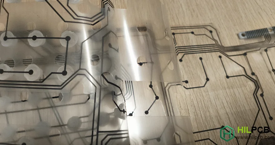
Rigid-Flex PCB: When Hybrid Construction Makes Sense
Rigid-flex construction combines rigid and flexible sections in a single integrated assembly, eliminating connectors between sections entirely.
When Rigid-Flex Makes Sense
Hybrid construction benefits specific keyboard designs. Complex assemblies with multiple interconnected boards. High-reliability requirements where connectors add failure risk. Space constraints where connector volume is problematic. Premium products justifying higher manufacturing cost.
Rigid-Flex Architecture
Typical keyboard rigid-flex configurations:
- Central Flex, Edge Rigid: Main board rigid with flex interconnects to peripherals.
- Bookbinder: Two rigid boards connected by flex hinge.
- Multiple Rigid Islands: Several rigid sections joined by flex.
- High-Density PCB for Keyboards Integration: Dense rigid sections with flex routing.
Design Transition Zones
Rigid-to-flex transitions require careful design. Gradual transition reduces stress concentration at boundaries. Anchor patterns secure flex section to rigid base. Coverlay design prevents delamination at transition. Testing validates transition reliability under expected stress.
Cost-Benefit Analysis
Rigid-flex requires significant investment. Higher fabrication cost than separate rigid and flex boards. Reduced assembly cost eliminates cable and connector assembly. Improved reliability may reduce warranty and service costs. Total cost comparison determines economic viability.
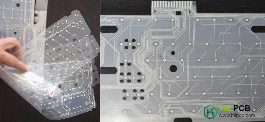
Flex PCB Manufacturing and Assembly for Keyboards
Flex circuit manufacturing differs from rigid PCB production, requiring specialized processes and handling throughout the production line.
1. Fabrication Considerations
Flex-specific fabrication requirements:
- Material Handling: Thin materials require careful handling throughout process.
- Registration: Maintaining alignment through processing steps.
- Coverlay Processing: Precise opening registration and lamination.
- Dimensional Stability: Account for material movement during processing.
2. Assembly Challenges
Flex PCB assembly presents unique challenges. Fixturing supports flexible material during component placement. Reflow profiles account for different thermal properties. Component placement accuracy on flexible substrates. Handling prevents flex damage throughout assembly process.
3. Quality Verification
Flex-specific inspection requirements:
- Bend Testing: Verify flexibility meets design requirements.
- Continuity Through Flex: Confirm conductors survive bending.
- Visual Inspection: Check for cracks, delamination, or damage.
- Keyboard PCB Assembly QA: Integrated flex testing in keyboard assembly.
Production Scaling
Flex circuit production scales with appropriate planning. Small Batch Assembly validates flex design before volume commitment. Tooling requirements may differ from rigid PCB production. Turnkey Assembly coordinates flex fabrication with keyboard assembly for seamless integration.
Whether implementing split keyboard interconnects or enabling innovative form factors, Flexible PCB for Keyboards technology expands design possibilities beyond rigid board limitations. Contact our engineering team to explore how flex circuits can enhance your keyboard design.
Common Questions
Why would a keyboard design use a flexible PCB instead of only rigid boards?
Flexible circuits help connect moving or space-constrained sections that are awkward to handle with rigid interconnects alone. They are especially useful when the product needs slimmer packaging, articulated geometry, or cleaner internal cable management.
What makes flexible keyboard PCBs harder to manufacture than standard rigid boards?
Flex materials need tighter control during fabrication, lamination, assembly support, and handling because thin substrates move more easily and can be damaged by poor process control. Quality checks also need to confirm that conductors and structures survive bending instead of only passing flat-board inspection.
What should be verified before a flexible keyboard PCB moves into production?
Teams should verify bend reliability, dimensional stability, coverlay and stiffener alignment, and assembly handling before release. Production is more reliable when the flex portion has been validated as a mechanical and electrical element together.