
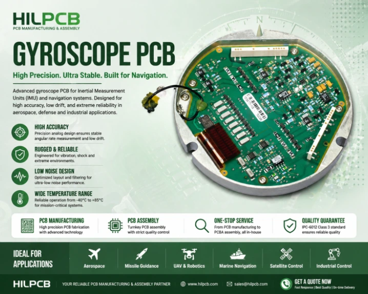
A gyroscope measures angular rate—how fast and in which direction a platform rotates. The global IMU market — valued at $22.6 billion in 2023 and projected to reach $35 billion by 2030 — depends on gyroscope PCBs that form the core of inertial measurement units (IMUs) enabling aircraft autopilots, missile guidance systems, satellite attitude control, autonomous vehicle navigation, and surgical robot orientation. The PCB interfaces with the sensing element, conditions and digitizes the signal, applies calibration and drift compensation, and outputs rotation data to the host navigation computer.
Inertial navigation technology is developed across the United States (Honeywell, Northrop Grumman), France (Safran, iXblue), Germany (Northrop Grumman LITEF), and the United Kingdom (Atlantic Inertial Systems). These firms require gyroscope PCBs with precision analog routing and environmental qualification matching military and commercial aviation standards.
What makes gyroscope PCB design uniquely challenging is measurement precision. A navigation-grade MEMS gyroscope must resolve angular rates below 0.01°/s with bias stability better than 1°/hour—requiring PCB electronics to add less noise than the sensor itself. Any electronic noise, thermal drift, or vibration artifact translates directly into navigation error accumulating over time.
HILPCB Manufacturing Capability: We fabricate gyroscope and IMU PCBs with precision analog layout for sub-μV noise floors, HDI construction for compact IMU modules, temperature-stable high-Tg materials, and IPC-6012 Class 3 qualification for defense and aerospace programs.
In This Guide
- MEMS Gyroscope PCB Interface Design
- Fiber-Optic and Ring Laser Gyro Electronics
- Drift Compensation and Calibration
- Multi-Axis IMU Integration and Environmental Design
- DFM, Testing, and Cost Analysis
- HILPCB Gyroscope PCB Manufacturing
MEMS Gyroscope PCB Interface Design
MEMS gyroscopes span a 100× performance range, and the PCB interface scales accordingly—from a basic digital connection to precision analog signal chains demanding laboratory-grade layout discipline.Consumer MEMS gyros (Bosch BMI270, TDK ICM-42688, STMicroelectronics LSM6DSO) integrate everything in one package. The PCB provides SPI or I²C connection, decoupling within 1 mm of power pins, and stress-free mechanical mounting per the datasheet.
Tactical/navigation MEMS gyros (Honeywell HG4930, Northrop Grumman LN-200A) provide analog rate output requiring a precision instrumentation amplifier (CMRR >100 dB, noise <5 nV/√Hz), anti-aliasing filter (100–500 Hz), and 24-bit sigma-delta ADC sampling at 1–10 kSPS.
At HILPCB, our analog gyroscope layouts implement the critical techniques that separate sensor-limited performance from noise-degraded measurement:
- Guard Traces: Surrounding the analog input intercepts surface leakage currents corrupting the high-impedance measurement path.
- Kelvin-Connected Sense Resistors: 4-wire connections eliminate trace resistance error from bias current measurement.
- Thermal Symmetry: Matched copper area on both sides of differential inputs prevents thermocouple-effect DC offsets.
- Dedicated Analog Ground: Single-point connection beneath the ADC prevents digital switching current from flowing through the analog path.
MEMS gyroscope performance is acutely sensitive to soldering stress—SMT assembly can bias output by several degrees per second. Use the manufacturer's reflow profile precisely, avoid PCB flexure during depaneling, and allow 24–72 hours of stress relaxation before calibration.
Fiber-Optic and Ring Laser Gyro Electronics
FOG and RLG technologies deliver 100–1000× better bias stability than MEMS—enabling GPS-free navigation for hours or days. Both require precision analog electronics pushing standard PCB fabrication to its limits.A fiber-optic gyroscope detects rotation via the Sagnac effect. The PCB includes SLD driver with intensity stabilization, phase modulator driver (50–200 kHz), photodetector transimpedance amplifier (TIA), and digital demodulation. The critical requirement is >80 dB isolation between modulator drive harmonics and the TIA—achieved through stripline shielding with continuous ground planes on multilayer constructions. The SLD driver requires dedicated low-noise regulation with <10 μVrms ripple.
Ring laser gyros use gas discharge in an optical cavity. The PCB provides discharge current regulation (1–5 mA, ±0.01% stability), dither motor drive, and fringe counting electronics. Current stability is paramount—0.01% change shifts gas refractive index, altering cavity resonance and introducing bias error. Precision current-sense resistors (±5 ppm/°C) and low-noise feedback amplifiers (<1 μV offset drift) are essential.
For both technologies, the final ADC must not limit achievable accuracy: 24-bit sigma-delta for navigation, input noise below 1–10 μVrms, and gain drift below the gyroscope's specified bias drift over temperature.
Drift Compensation and Calibration
Gyroscope bias drift—the slow wandering of zero-rate output—is the fundamental accuracy limitation in inertial navigation. Every degree/hour of uncompensated drift equals 1 nautical mile of position error per hour of dead-reckoning.MEMS bias shifts 0.01–0.1°/s/°C for tactical-grade sensors. Compensation requires a precision temperature sensor (±0.1°C) within 5 mm of the gyro package, with polynomial correction from factory calibration stored in non-volatile memory. The temperature sensor must track gyro package temperature, not ambient air—thermal vias connecting sensor and gyro pads through inner copper planes improve coupling, while thermally symmetric copper fill prevents localized gradients. Heat sources must be kept >20 mm from the gyroscope.
The PCB's electronic noise contribution to Allan variance is reducible through three mechanisms: power supply noise (multi-stage LC filtering with cutoff below measurement bandwidth), ADC quantization noise (oversampling with digital decimation), and PCB leakage current (guard traces and clean fabrication per IPC-TM-650 contamination limits).
Navigation-grade IMUs require factory calibration on a precision rate table at 5+ temperature points. The PCB must provide a calibration interface (serial, JTAG, or test points) accessible without enclosure disassembly.
Multi-Axis IMU Integration and Environmental Design
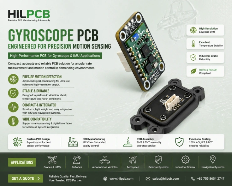
A complete IMU integrates 3 gyroscopes, 3 accelerometers, and optionally 3 magnetometers on a single board—maintaining individual sensor performance while managing crosstalk, vibration, and compact packaging that often demands [rigid-flex](/products/rigid-flex-pcb/) construction for 3D folded assemblies.Mechanical coupling through the PCB substrate transfers vibration energy between orthogonal sensors—mitigated by rigid board construction, manufacturer-specified mounting, and stiffener plates beneath sensor arrays. MEMS gyroscopes rectify vibration at specific frequencies into DC bias error (VRE), addressed by elastomeric isolators (100–200 Hz), thick board construction pushing resonances above the isolation bandwidth, and digital comb filters targeting known vibration frequencies.
Temperature gradients create differential thermal expansion biasing gyroscope output. Thermally symmetric copper fill and >20 mm separation from heat sources provide uniform thermal environment. For highest accuracy, active TEC regulation within a thermally controlled housing isolates sensors from ambient swings.
Defense applications require MIL-STD-810H qualification—surviving 5–2000 Hz random vibration at 3–5G RMS without component failure or significant bias drift.
DFM, Testing, and Cost Analysis
Precise sensor orientation relative to the board reference frame is critical—mounting angle error directly translates to navigation error. The PCB must provide flat, stress-free mounting areas with precision reference features for system alignment. Reflow profile records are mandatory for traceability, as excessive temperature shifts sensor calibration through residual package stress.| Component | Consumer IMU | Tactical IMU | Navigation IMU |
|---|---|---|---|
| Gyroscope | $2–5 MEMS | $50–200 MEMS | $1000+ FOG |
| PCB layers | 2–4 | 6–8 | 8–12 |
| Material | Standard FR-4 | High-Tg FR-4 | Low-loss/High-Tg |
| Total PCB cost | $5–15 | $50–200 | $500–2000 |
Why IMU and Navigation OEMs Partner with HILPCB
Since 2017, HILPCB has delivered over 180 gyroscope and IMU PCB programs for inertial navigation companies across the United States, Germany, France, the United Kingdom, and Canada. Our platform supports consumer MEMS on 4-layer FR-4 through navigation-grade FOG on 12–16 layer multilayer constructions with low-CTE materials.
Our engineering team reviews IMU designs for sensor mounting stress, vibration resonance, power supply noise, and analog signal integrity. For rigid-flex IMU assemblies, our polyimide processing ensures reliable flex transitions under continuous rotation and thermal cycling. Every board ships with IPC-6012 Class 3 certification and full material traceability. From prototype builds through volume production, our process consistency maintains the sub-μV noise floor your inertial application demands.
Gyroscope PCB FAQ
How does PCB layout affect MEMS gyroscope bias stability?
Poor PCB layout can introduce mechanical stress, thermal gradients, and electrical noise, all of which manifest as bias drift. Asymmetric copper distribution causes uneven thermal expansion, while poor power filtering injects noise into the analog measurement bandwidth.
Why is strict adherence to reflow profiles critical for IMU PCBs?
MEMS gyroscope packaging is extremely sensitive to residual thermomechanical stress. Deviating from the manufacturer's specified reflow profile can induce permanent strain on the MEMS structure, fundamentally altering its factory calibration and null bias beyond the capability of software compensation.
How do rigid-flex constructions benefit multi-axis IMU assemblies?
A rigid-flex PCB allows the orthogonal mounting of X, Y, and Z-axis gyroscopes on a single continuous circuit. This eliminates the weight, reliability issues, and impedance variations of physical connectors, while enabling the sensors to be precisely folded into a compact, 3D cubic enclosure.