
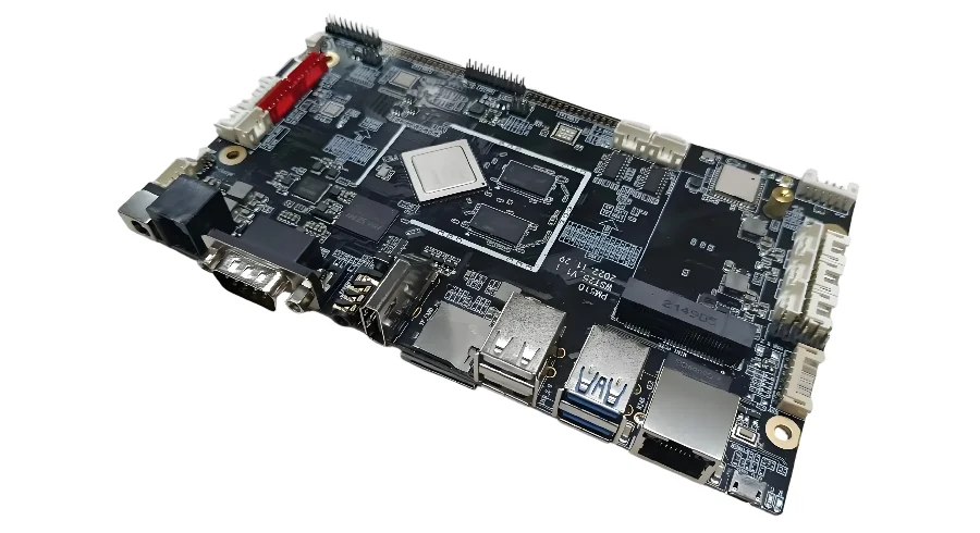
- Lane control electronics should be reviewed as safety-relevant outdoor control hardware, not as a generic industrial controller with LEDs and communication ports.
- The first checks are signal logic, fail-safe state behavior, power protection, communication architecture, environmental exposure, and how field maintenance will be handled.
- Most failures show up as ambiguous signal behavior, unstable communication, power-event damage, enclosure-driven corrosion, or weak fault handling during lane-open and lane-closed transitions.
- A credible design separates display drive, control logic, sensing, communications, and field I/O so the failure of one function does not create unsafe lane indications.
- Prototype success depends on freezing the operating logic and field conditions early, especially when the board must drive overhead lane-use signals or connected roadside equipment.
Lane control electronics are the PCB and PCBA systems used to command, communicate, and supervise lane-open or lane-closed indications in transportation infrastructure. In practice, that means the hardware has to support clear signal behavior, coordinated control, outdoor power and communication resilience, and fault handling that defaults to a safe and understandable state.
Contents
- What to review first on lane control electronics
- Key design and validation rule table
- Early engineering trade-off table
- How signal logic, control architecture, and fail-safe behavior interact
- How outdoor deployment and maintenance planning should be handled
- What teams should lock down before deployment-oriented prototype release
- FAQ
- Next steps
- References
- Author and review
What to review first on lane control electronics
Lane control systems are not only display products. They are field-control systems that influence how drivers interpret lane availability. That makes hardware clarity and fault behavior more important than feature count.The first review points are usually:
- what lane indications the system is allowed to display and how those indications are coordinated across the controlled roadway section
- whether the controller has a defined fail-safe behavior if power, communication, sensing, or output stages fail
- how outdoor power disturbances, lightning exposure, moisture, contamination, and temperature swings are handled
- whether communications, local I/O, diagnostics, and display drive sections are isolated or partitioned clearly enough
- how field maintenance, replacement, logging, and version control will work after deployment
For boards intended for outdoor transportation infrastructure, it is usually worth reviewing high Tg PCB, multilayer PCB, and turnkey assembly assumptions before release.
Key design and validation rule table
| Rule / parameter | What to check first | Why it matters | How to verify | If ignored | | --- | --- | --- | --- | --- | | Allowed signal logic | Match hardware output logic to the approved lane-use indications | Lane-control systems must not present conflicting meanings | Logic review and state-table review | Unsafe or ambiguous field behavior | | Fail-safe state | Define what the system does under loss of control, comms, or output fault | Safety depends on fault behavior more than normal behavior | FMEA review and bench-fault test plan | Hardware failure creates misleading lane status | | Output-stage separation | Keep display drive and controller logic partitioned appropriately | Output failures should be containable and diagnosable | Schematic review and power review | One fault propagates across functions | | Outdoor power and surge margin | Review transient protection, grounding, and field wiring exposure | Roadside electronics face harsher electrical events than lab equipment | Protection review and environmental validation plan | Field failures rise sharply | | Communication robustness | Confirm how central control, local diagnostics, and device coordination survive noise or link loss | Lane logic often depends on coordinated behavior | Interface review and network-failure test plan | Intermittent state loss and unstable operation | | Serviceability and traceability | Make replacement, logging, and revision tracking practical for field maintenance | Infrastructure hardware must be supportable over time | Connector review, logging review, serial-trace review | Troubleshooting becomes slow and error-prone |Early engineering trade-off table
| Design choice | Usually stronger for | Main trade-off | What to confirm early | | --- | --- | --- | --- | | Centralized control emphasis | Better coordination and simpler oversight | More dependence on communications availability | Link reliability and fallback behavior | | Stronger local fail-safe logic | Better resilience during network or upstream faults | More local logic and validation burden | Approved autonomous behavior | | More modular output and I/O stages | Easier maintenance and fault isolation | Higher hardware complexity and cost | Service model and spare strategy | | More environmental hardening | Better field life in harsh roadside conditions | Higher enclosure, coating, and test cost | Real installation environment |How signal logic, control architecture, and fail-safe behavior interact
Lane control electronics are only useful when the hardware behavior stays understandable during both normal and faulted operation. That is why architecture matters as much as component selection.Three review questions usually matter most.
1. Are the lane indications constrained to approved meanings?
The hardware should not allow arbitrary combinations that create confusion in the field. The controller, outputs, and supervisory logic should reflect the actual lane-use indication model that the system is allowed to present.
2. Is the fail-safe behavior defined in hardware terms?
It is not enough to say the system is fail-safe. The team should know what happens on controller reset, communication timeout, output short, or field-power disturbance. That behavior should be testable on the bench.
3. Is the board partitioned for diagnosis and containment?
Display drive, controller logic, communications, protection, and service interfaces should not be merged casually. PCB viewer and Gerber viewer review often makes these boundaries easier to validate before field build.
How outdoor deployment and maintenance planning should be handled
Lane control electronics are deployed into weather, contamination, transient stress, and long maintenance cycles. A design that works indoors can still fail quickly outside if the deployment path is not considered early.The most common planning questions are:
- whether the enclosure, connectors, coating strategy, and grounding concept match the actual installation exposure
- whether power input protection and communication ports are sized for the real field environment rather than for a bench supply
- whether logs, configuration versioning, and local diagnostics are adequate for field support
- whether replacement boards can be installed safely without configuration ambiguity
If the design is still early, PCB prototype, quick-turn PCB, and turnkey assembly planning usually saves more time than refining application logic without hardware service assumptions.
What teams should lock down before deployment-oriented prototype release
The first article should prove the control behavior, not only the board assembly. Before release, the team should know what the hardware is supposed to demonstrate in a realistic field simulation.A practical release checklist usually includes:
- Signal-state model frozen
Define which lane indications are supported and which combinations are prohibited. - Fail-safe behavior approved
Freeze controller, comms, and output-fault behavior before layout release. - Field-interface plan approved
Confirm power, communication, grounding, diagnostics, and service-access assumptions. - Environmental validation plan defined
Decide what temperature, moisture, power-event, and service-condition checks the prototype must survive. - Revision and deployment data aligned
Keep firmware, board revision, connector mapping, and maintenance notes synchronized. A BOM viewer review helps prevent unnoticed changes in field-facing parts.
FAQ
What is the first thing to check on lane control electronics?
Start with the allowed signal logic and fail-safe state model. Those two decisions usually determine whether the rest of the hardware architecture is acceptable.
Why is fail-safe behavior more important than normal operation on this kind of board?
Because lane control hardware influences driver behavior in the field. A rare fault state can matter more than thousands of hours of normal operation if it creates the wrong lane indication.
Is a lane control PCB mainly a display driver board?
No. It is usually a control, communication, protection, and output system that happens to drive lane indications. Treating it as only a display board hides the real safety and field-service risks.
Why do outdoor deployment details matter so much?
Because roadside electronics face moisture, contamination, transient power events, and longer maintenance intervals. Those conditions can dominate field reliability.
What should be frozen before the first deployment-oriented prototype release?
Freeze the lane indication model, fail-safe logic, field-interface assumptions, validation plan, and the exact revision data that the prototype represents.
Next steps
If you are developing lane control electronics or another roadside control board, the most useful next step is usually to review signal logic, fail-safe behavior, field interfaces, and maintenance assumptions as one system.HILPCB can support that process through:
- High Tg PCB review for outdoor and thermally stressed control electronics
- Multilayer PCB planning when control, communication, and power domains need separation
- Turnkey assembly support when field hardware needs controlled build and traceability
- PCB prototype and quick-turn PCB support for early field-oriented validation
- Request a quote when your control logic, interface plan, and deployment assumptions are ready for review