
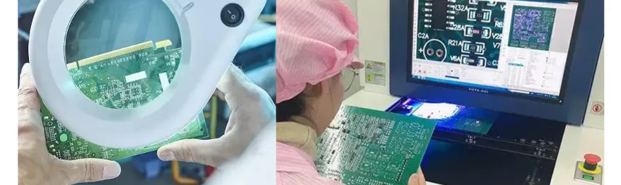
LED PCB quality depends on controlling the emitter, driver, board, assembly process, and test conditions together. An AOI image can show placement or visible solder defects; it cannot establish light output, junction temperature, or complete luminaire safety. HilPCB supports LED PCB manufacturing, assembly inspection, and project-defined electrical testing. Agree the optical, thermal, and reliability validation scope alongside the manufacturing acceptance plan so each result answers a specific release question.
Incoming Material Inspection and Verification
Incoming inspection should match the approved BOM, construction, supplier documentation, and risk-based sampling plan.
Substrate Material Verification: Check material identity, thickness, surface condition, and the specified lot documents. For metal core PCBs, distinguish the dielectric's thermal conductivity and thickness from the metal core and complete thermal path. For ceramic PCBs, identify the ceramic grade, metallization, dimensional tolerances, and required electrical insulation evidence. FR4 PCBs also need suitable surface cleanliness and finish for soldering. Agree which properties rely on supplier certificates, incoming measurements, or construction qualification; these are different forms of evidence.
LED Component Qualification: LED quality directly affects the finished light:
- Verify the exact part, bin code, and supplier binning conditions against the approved color and brightness requirements
- Check forward voltage at the defined test current and temperature; a different operating point can change the result
- Review package thermal resistance with its stated reference points and test conditions before using it in a board thermal model
- Review LED package LM-80 data where available; TM-21 projections do not certify the PCB or complete luminaire lifetime
Define lot sampling, component provenance, moisture sensitivity handling, storage, and release criteria before assembly. Supplier records and inspection help manage counterfeit risk; a visual check alone cannot establish authenticity.
Chemical and Process Material Control: Solder paste, flux, and cleaning chemicals need controlled handling:
- Verify paste condition and viscosity where the supplier's process calls for it, alongside storage, thawing, mixing, and stencil performance
- Confirm flux compatibility and wetting through the approved material and reflow process
- Monitor cleaning chemistry and contamination using a method suitable for the assembly and its residues
- Track shelf life, opened-container life, and exposure limits to avoid using expired or mishandled materials
In-Process Quality Monitoring
Inspection at defined process stages catches defects while correction is still practical.
PCB Fabrication Controls
Each fabrication step has different acceptance questions:
- Post-Lamination: Verify the specified construction and dielectric thickness; thermal performance also depends on material properties, heat spreading, interfaces, and the final cooling arrangement
- Post-Drilling: Inspect hole location and quality before plating
- Post-Plating: Verify copper and plated-hole requirements; current capacity also depends on conductor geometry and the permitted temperature rise
- Post-Etching: Measure trace width and spacing against the approved design and fabrication tolerances
- Post-Solder Mask: Check registration, coverage, and specified thickness without obscuring solderable or optical keepout areas
For high thermal PCBs, confirm the interface surfaces and thermal stack alongside the board dimensions. Optical inspection, applicable electrical tests, and selected coupons or sections address different fabrication defects. First article review establishes the construction and inspection baseline before repeat production; control charts can then track selected process parameters.
Assembly Process Monitoring
SMT assembly quality depends on consistent process execution:
- Solder Paste Inspection: Measure deposit volume, height, area, and placement with the selected SPI process
- Pre-Reflow AOI: Check component presence, polarity, and alignment where this inspection stage is used
- Post-Reflow AOI: Inspect visible joints and placement; hidden joints may need selected X-ray inspection or another agreed method
- In-Circuit Testing: Check accessible electrical nodes and components within fixture coverage; functional testing separately checks powered behavior against its test specification
HilPCB's SMT assembly route includes SPI, AOI, and project-selected X-ray and electrical testing. Define the coverage, sampling, rework, and retest rules rather than applying every method to every order. Agree how board or lot identity links to the retained inspection and test results. For HDI PCBs, placement inspection does not establish buried microvia integrity: fabrication qualification, applicable coupons or sections, and electrical checks have separate roles.
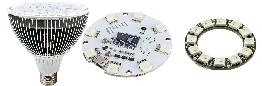
Comprehensive Testing Protocols
Select methods by the failure modes and release requirements they can actually detect.
Electrical Testing Suite: Beyond bare-board continuity, assembly validation may include:
- Insulation resistance between defined circuits and a conductive substrate where the construction requires isolation
- High-potential testing at approved points and settings when specified; board inspection cannot establish complete luminaire safety
- Current-path voltage drop and temperature rise under the defined load and cooling conditions
- Impedance checks for circuits whose interfaces require controlled impedance
- Power cycling under specified on/off, load, and thermal conditions
A repeatable fixture needs a revision-controlled test program, limits, calibrated measurement path, and a defined response to failures. Specify record content, lot or serial mapping, retention period, and delivery format in the order. Our Gerber viewer helps inspect file layers and visible geometry before release; it does not verify the BOM, circuit function, stackup performance, or assembled product.
Thermal Performance Validation: Temperature measurements need a defined reference and operating state:
- Use a thermal camera to map exposed surface temperatures with appropriate emissivity and reflection controls; it does not directly measure an enclosed LED junction
- Estimate junction temperature using the package supplier's approved reference-point method and applicable thermal parameter, or a suitable validated measurement method
- Map heat distribution across LED arrays, drivers, connectors, and thermal interfaces at the stated current, duty cycle, ambient, and cooling arrangement
- Use thermal cycling to investigate specified failure mechanisms and compare constructions, with the profile and acceptance criteria recorded
- Reserve thermal shock testing for applications and qualification plans that require that stress
Compare simulation with measurements at matching locations and boundary conditions. Junction-to-ambient thermal resistance depends on the assembly and environment; a package figure cannot replace the board, interface, housing, and cooling model. Cree LED's thermal management guidance explains these package and measurement relationships. Accelerated results need a justified model before they can support a field-life projection.
Optical Quality Verification: Specify the optical test provider, fixture, operating temperature, drive state, calibration, and acceptance limits for:
- Luminous flux measured with an appropriate calibrated integrating sphere or photometric setup
- Color temperature and chromaticity coordinates
- Color rendering index for white LEDs
- Beam angle and intensity distribution
- Uniformity across LED arrays
Spectral and photometric reports should identify the tested configuration, including lenses or diffusers when relevant. Compare batches under the same conditions. These tests may form a separate module or complete-light qualification scope; they are not implied by a bare-board or standard assembly order.
Environmental and Reliability Testing
Qualification and production screening have different purposes. Choose stresses from the actual installation, materials, failure mechanisms, and applicable product requirements.
Environmental Stress Testing
- Temperature/Humidity: Define temperature, humidity, duration, bias, specimen configuration, and leakage or functional acceptance criteria
- Thermal Cycling: Define temperature limits, ramp or transfer conditions, dwell, cycle count, and the joints or interfaces being assessed
- Salt Spray: ASTM B117 provides a controlled salt-fog environment; the product specification must set exposure and evaluation criteria, and field corrosion life needs separate supporting evidence
- Vibration/Shock: Select a method and severity appropriate to the installation and mounting, with connector, fastener, and functional checks before and after exposure
- UV Exposure: Define spectrum, dose, temperature, and the optical or material property being evaluated, particularly for exposed lenses, coatings, or plastics
Record specimen construction, test method and revision, sample plan, deviations, and pass/fail results. Failed samples should feed a documented investigation and any required requalification after material or process changes.
Burn-In and Life Testing
An agreed screening plan may include:
- Elevated-temperature operation for a duration justified by the components, thermal limits, and screening objective
- On/off cycling with the drive state and timing recorded
- Operation at a defined current and duty cycle within the approved component and assembly limits, with temperature monitoring
- Light-output degradation measurements under consistent optical conditions
- Driver stability checks during continuous operation and after interruptions
Sampling, screening time, and measurement coverage affect both cost and evidence strength. Weibull or other life models require suitable failure data, censoring treatment, and a justified failure mechanism. Compare production escapes and field returns with screening results to assess whether the screen is useful; burn-in alone does not establish a warranty life.
Statistical Process Control Implementation
Use process data to distinguish drift, variation, and recurring defect patterns.
Control Chart Monitoring: Select measurable parameters and an appropriate collection interval:
- Solder paste thickness after printing
- Component placement accuracy
- Reflow temperature profiles
- Solder joint quality metrics
- Test parameter measurements
Control limits describe process behavior; specification limits define acceptance. Investigate control-chart signals before reporting capability. Cpk compares a stable process with its specification limits and also depends on adequate data and distribution assumptions; Cpk alone does not demonstrate stability. See NIST's process capability guidance.
Defect Analysis and Prevention: Structured investigation connects evidence to a verified corrective action:
- Pareto analysis identifies primary defect types
- Fishbone diagrams explore causation
- 8D problem-solving for customer complaints
- FMEA proactively identifies risks
- Corrective action tracking ensures closure
Use supplier feedback and cross-functional review to test proposed causes. Verify the correction on subsequent production and preserve the approved change and release records.
Manufacturing and Release Support for LED PCB Projects
HilPCB offers metal-core, ceramic, FR-4, and compatible HDI constructions alongside SMT/THT assembly, sourcing, programming, and agreed electrical or functional testing. SMT capability includes 0201 placement and 0.4 mm pitch, with finer features reviewed by project. SPI, AOI, and selected X-ray inspection help address different assembly defects; inspection and first article records support a repeatable production baseline.
Our turnkey assembly route connects the approved BOM and material supply with fabrication, assembly, and test planning. Thermal engineering and box-build integration can also address the board-to-interface-to-housing path, harnesses, and specified screening. State which optical, environmental, and life tests are supplied by the customer or an assigned specialist, and which manufacturing records should accompany the shipment.
Planning an LED PCB quality review?
Send the fabrication files, stackup, BOM/AVL, LED part and bin requirements, drive current and duty cycle, cooling arrangement, and optical or insulation acceptance limits. Include the fixture, firmware, test coverage, sample plan, and required lot or serial records. These inputs let the quotation separate board fabrication, assembly inspection, functional test, and any additional qualification work, then establish a first article and repeat-order release plan.
HILPCB's quality support can include closed-loop SPC and full lot traceability, material and thermal verification, LED-lot and counterfeit-material controls, integrating-sphere and spectral validation, and a quoted option for 100% SPI/AOI/AXI production-inspection coverage where the assembly and line support those methods. APQP/PPAP support, certificates of conformance, quality-response and containment records, and specified burn-in or environmental tests can be included when agreed for the program. The delivered records identify actual lot and test scope; they do not replace device qualification or make Cpk a guarantee of future process stability.
Frequently Asked Questions
Q1: What quality standards apply to LED PCBs?
Specify the applicable IPC fabrication and assembly documents, revisions, acceptance class, and any product-specific requirements in the order. For a required quality-system certificate, verify the current document's legal entity, site, and scope against the intended supply route.
Q2: How is LED color consistency controlled?
Use the approved LED part and bin, supplier binning conditions, and agreed incoming controls. Define the chromaticity target or MacAdam ellipse tolerance, drive current, temperature, optics, sampling, and measurement method for the assembled light; bin selection alone does not establish the complete light's color result.
Q3: What documentation should an order include?
Agree the first article, reflow-profile or inspection records, electrical or functional test results, lot or serial traceability, and any required Certificate of Conformance during quotation. Specify record format and retention, plus separate optical or reliability reports where those tests are included.
Q4: Can the project include automotive quality requirements?
Provide the customer-specific requirements, applicable site and program qualification, and requested APQP/PPAP deliverables for review before release. Component qualification and vehicle or lighting-system validation remain distinct from bare-board and assembly acceptance.
Q5: How are quality issues handled?
Identify the affected lot, revision, failed test, and operating conditions so the team can define containment and investigate the cause. Track corrective action, rework or replacement disposition, retest results, and verification on subsequent production, with change control for the approved correction.