
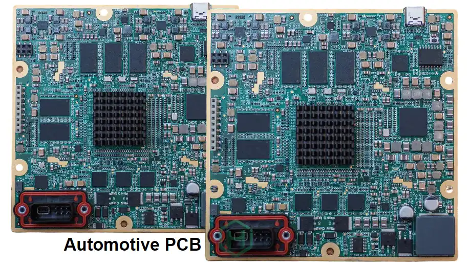
As an automotive reliability engineer responsible for salt spray, thermal shock, and wide-temperature lifetime evaluations, I know that in the harsh environments of ADAS and EVs, a single ECU failure can lead to catastrophic outcomes. LiDAR sits at the heart of perception, and the reliability of its interface board directly determines system safety and performance. That’s why a comprehensive, rigorous LiDAR interface board checklist is not just a design-and-manufacturing guide—it is the quality and reliability foundation across the entire product lifecycle. The checklist ensures that every step, from concept through mass production, meets the automotive industry’s demanding requirements for safety, durability, and consistency.
Dual constraints of AEC-Q and ISO 26262: build reliability from the source
In automotive electronics, every product must be developed within strict regulatory frameworks. For a LiDAR interface board, the first mission of the LiDAR interface board checklist is to ensure the design, component selection, and manufacturing flow fully comply with the AEC-Q series and ISO 26262 functional safety.
ISO 26262 functional safety requirements: LiDAR systems are commonly assigned higher Automotive Safety Integrity Levels (ASIL) such as ASIL-B or ASIL-C. This means LiDAR interface board design must perform system-level safety analysis, including HARA, Functional Safety Concept (FSC), and Technical Safety Concept (TSC). The design must consider diagnostic coverage (DC) and fault metrics (FM), using measures like redundancy, watchdog circuitry, voltage/current monitoring, etc., so the system transitions to a safe state under random hardware failures.
AEC-Q component-level reliability: The checklist requires that all components—especially semiconductors (AEC-Q100), passive parts (AEC-Q200), and discrete semiconductors (AEC-Q101)—be automotive qualified. This ensures components operate reliably across the automotive temperature range (typically -40°C to 125°C), high humidity, and strong vibration. For a high-speed LiDAR interface board, selection of high-speed transceivers, FPGA, and processors is particularly critical; performance degradation at elevated temperature must be thoroughly assessed.
OEM-specific specifications: Beyond generic standards, OEMs usually impose even stricter internal requirements. The checklist must include a line-by-line interpretation and mapping of the target customer’s specs to ensure electrical performance, EMC/EMI, thermal, and mechanical requirements meet or exceed expectations.
APQP/PPAP core processes: consistency and traceability from prototype to mass production
An effective LiDAR interface board checklist should deeply integrate the automotive quality tools APQP and PPAP. This framework ensures seamless transition and quality control from concept to mass production.
APQP splits development into five phases—from planning, product design & development, process design & development, product & process validation, to feedback/evaluation/corrective action. In the LiDAR interface board prototype stage, APQP is already active, using DFMEA to identify potential design risks early.
Then comes PPAP—the final verification of manufacturing process capability. The supplier must submit a complete package containing 18 core elements to prove the process is stable, controlled, and capable of consistently producing parts that meet design requirements. Key elements include:
- Process Flow Diagram: clearly shows every step from incoming materials to finished goods shipment.
- PFMEA: identifies potential failure modes in manufacturing and defines prevention/detection controls.
- Control Plan: details key product characteristics (KPC), measurement equipment, sample size, frequency, and escalation handling at each production step.
- MSA: validates measurement system accuracy and repeatability.
- SPC: demonstrates process capability via indices such as Cpk and Ppk (typically Cpk > 1.67).
Whether for high-volume production or LiDAR interface board low volume pilot builds, PPAP is indispensable. It ensures every delivered PCB comes from a validated and approved manufacturing process. HILPCB’s prototype assembly service fits APQP perfectly, providing high-quality LiDAR interface board prototype builds and laying a solid foundation for PPAP submission and later mass production.
🛡️ LiDAR interface board lifecycle quality matrix: APQP to PPAP
Define LiDAR reliability targets and regulatory compliance requirements. Start an initial DFMEA risk assessment and set up the core team and development milestones.
Execute LiDAR interface board design. Introduce components compliant with AEC-Q100/Q200 and complete design verification (DV) testing and stackup optimization.
Develop Control Plan and PFMEA. Design dedicated fixtures to ensure repeatable PCB assembly processes and strong Cpk potential.
Run Pilot Run builds. Execute comprehensive LiDAR interface board testing (environment/EMC/functional) and collect SPC data to validate process capability.
Submit the PPAP Level 3 package. After customer approval, start full-rate Run@Rate production, continuously monitor PPM-level defect rates, and drive continuous improvement.
Harsh environment and reliability tests: validate survival under extreme conditions
As a reliability engineer, LiDAR interface board testing is the core of my work and the final proving ground for design and manufacturing quality. The checklist must include a complete, stringent test matrix that simulates every extreme environment a vehicle may encounter across its lifecycle.
- Temperature cycling and thermal shock (TC/TS): a key test for solder-joint reliability and thermo-mechanical material matching. Typical conditions are -40°C to +125°C for 1000 cycles (or more). The goal is to expose solder fatigue, delamination, or micro-cracks caused by CTE mismatch across materials.
- Temperature humidity bias (THB): apply operating voltage under high temperature/high humidity (e.g., 85°C/85%RH) for 1000 hours. This accelerates electrochemical migration (ECM) risk and validates insulation and corrosion resistance.
- Mechanical vibration and shock: simulates random vibration and shock from rough-road driving, exposing solder fatigue on leads, connectors, and large components.
- Salt spray (Salt Spray): evaluates corrosion resistance of the PCB and its coating (Conformal Coating) in salty, humid environments—critical for ECUs mounted under-chassis or on external body locations.
- Power-line transient immunity: per ISO 7637-2, simulates load dump, crank transients, and other disturbances in the vehicle power network to validate power integrity robustness.
All LiDAR interface board testing items must be completed in the design verification (DV) and product validation (PV) stages, and the results are key inputs for PPAP approval.
High-speed signal integrity (SI) and power integrity (PI) challenges
Modern LiDAR generates and processes massive point-cloud data, placing extremely high demands on interface-board data rates. Therefore, the high-speed LiDAR interface board portion is the most technically intensive part of the checklist and must focus on SI and PI.
- Impedance control and matching: high-speed differential signals (e.g., LVDS, MIPI, SerDes) require tight transmission-line impedance control. The checklist must specify that stackup design, material selection (such as low-Df high-speed PCB laminates), and routing rules all ensure impedance continuity to prevent reflections and distortion.
- Crosstalk and EMI/EMC: high-density routing makes crosstalk a primary challenge. Rules must define parallel spacing, reference-plane integrity, and shielding strategies for sensitive nets. Solid grounding and power filtering are fundamentals for suppressing EMI and meeting EMC.
- PDN design: core devices such as FPGA and processors demand fast transient response from power rails. PDN design should use simulation to keep rail ripple and noise within limits under all loads—typically requiring careful decoupling placement and wide power/ground planes. For increasingly complex LiDAR interface board design, adopting HDI PCB can improve routing and power distribution efficiency.
Key reminders: high-speed design best practices
- Material selection: prioritize laminates with low dielectric constant (Dk) and low dissipation factor (Df) to reduce signal attenuation.
- Stackup design: use a symmetric, balanced stackup; place high-speed signal layers between solid reference planes (stripline).
- Routing rules: follow the 3W rule (spacing > 3× trace width), avoid 90° corners, and keep differential pairs length-matched.
- Via optimization: use backdrill or blind/buried via techniques to reduce via stubs and reflections.
- Power integrity: place sufficient types/quantities of high-frequency/low-frequency decoupling capacitors close to IC power pins.
Manufacturing process control and traceability: full-chain quality from SPC to 8D
Even with a perfect design, nothing works without a stable, controlled manufacturing process. In execution of the LiDAR interface board checklist, strict process monitoring is the focus.
- SPC: continuously monitor key parameters such as drilling accuracy, etch line width, lamination thickness, and impedance values. Control charts (X-bar, R-chart) help detect abnormal variation in real time and enable intervention before large scrap occurs.
- Cpk/Ppk: periodically evaluate how well the process meets spec tolerances. Automotive programs commonly require Cpk > 1.67 for critical parameters, reflecting extremely small drift and variation with high quality consistency.
- Complete traceability: mandatory for automotive-grade products. A full trace chain must link raw-material lots, equipment, operators, process parameters, and finished goods. When issues occur, affected lots can be identified quickly for precise recall rather than broad actions.
- 8D problem solving: major quality issues must trigger a structured 8D flow. This ensures systematic containment, root-cause identification, and permanent corrective actions—while closing lessons learned back into PFMEA and Control Plan to prevent recurrence.
Mass-production launch and continuous improvement: Run@Rate and lifecycle management
The final step of development is a smooth transition from pilot builds to mass production. Checklist closure focuses on verifying production readiness and driving lifecycle continuous improvement.
- Run@Rate: before formal mass production, the supplier runs production at mass-production takt using mass-production equipment, people, and processes—witnessed by the customer—to validate stable delivery under real throughput pressure. This is the ultimate audit of the production system.
- Smooth transition from low volume to mass production: for LiDAR interface board low volume programs, management models can differ from high volume. When scaling, supply chain, automation, test capacity, and logistics must keep pace. HILPCB’s Turnkey Assembly helps manage the full flow from PCB fabrication to component sourcing, SMT, and testing—ensuring smooth transitions between phases.
- Continuous improvement: after release, quality work continues. By collecting manufacturing data, customer feedback, and field-failure data, we continually optimize design and manufacturing—reflecting the automotive Zero Defect culture.
Conclusion
In summary, a comprehensive LiDAR interface board checklist is a lifeline for ensuring the safety and reliability of automotive ADAS and EV systems. It is not merely a list of to-dos, but an integrated management system combining ISO 26262 functional safety, AEC-Q reliability standards, APQP/PPAP quality processes, harsh-environment testing, high-speed design rules, and lean manufacturing practices. From the initial LiDAR interface board design concept, through iterative LiDAR interface board prototype builds, to final mass-production delivery, every checklist section is challenging. As reliability engineers, our mission is to execute and continuously improve this checklist to eliminate risks early—and provide a solid, dependable hardware foundation for the future of intelligent driving.
Common Questions
Why is a LiDAR interface board checklist so important for automotive programs?
Because the board sits inside a safety-relevant vehicle system, teams need a structured way to control functional safety, reliability, EMC, manufacturability, and traceability from prototype through PPAP and mass production. The checklist helps prevent critical gaps from being missed.
Which validation tests are most important for a LiDAR interface board?
Typical high-priority tests include temperature cycling, thermal shock, humidity bias, vibration, mechanical shock, salt spray, and vehicle power transient immunity. These tests verify that the board can survive real automotive operating conditions over time.
Why do SI and PI matter so much on a LiDAR interface board?
Modern LiDAR platforms handle high-speed data links and dense processing electronics, so impedance discontinuities, crosstalk, and power noise can quickly degrade performance. Careful stackup planning, routing control, and PDN design are essential to keep signals clean and stable.
What manufacturing controls help qualify these boards for volume production?
Automotive programs usually require SPC monitoring, Cpk or Ppk capability targets, full lot traceability, disciplined 8D problem solving, and Run@Rate verification before launch. These controls prove that the factory can repeatedly build the design at production quality.