
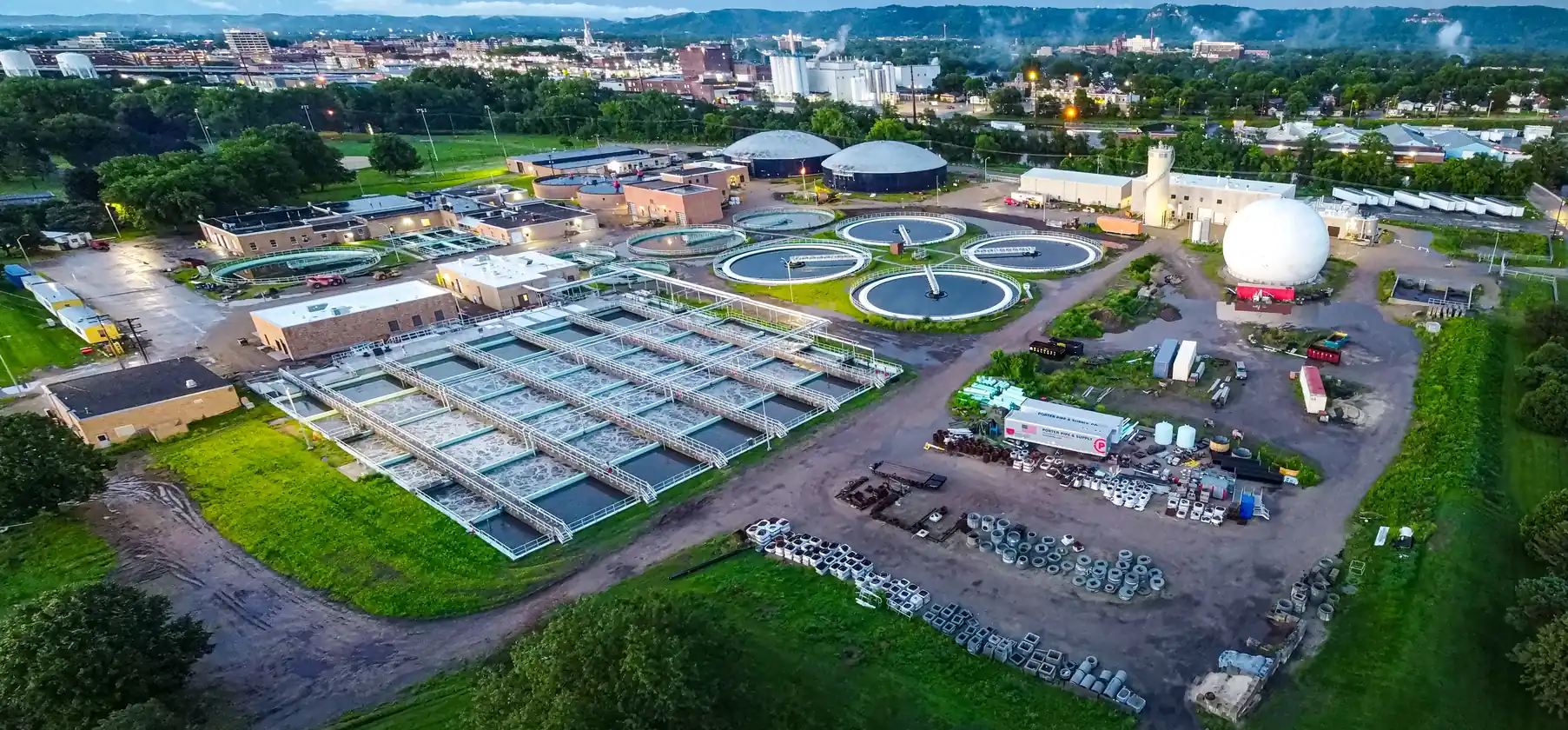
A Moving Bed PCB is the control and monitoring board used inside Moving Bed Biofilm Reactor (MBBR) equipment and related water-treatment systems. It does not remove pollutants by itself. Instead, it supports the electronics that keep the biological process measurable and controllable: dissolved oxygen sensing, pH/ORP measurement, aeration control, dosing-pump commands, filtration coordination, UV disinfection control, industrial communications, alarms, and data logging.
That distinction matters. In a wastewater plant, final effluent quality depends on process design, hydraulic loading, media condition, temperature, operator settings, calibration, maintenance, and regulatory sampling. The PCB can support stable control and traceable measurement, but it cannot independently guarantee discharge compliance.
For equipment developers, the practical challenge is to build a board that can survive humid, corrosive, electrically noisy environments while still measuring weak sensor signals accurately. This guide explains the design, manufacturing, and validation choices that matter when sourcing a Moving Bed PCB or environmental monitoring PCBA for MBBR systems, filtration units, dosing skids, UV sterilization equipment, and remote water-quality monitoring nodes.
Key Takeaways
- A Moving Bed PCB should be designed as an industrial control and measurement platform, not as a generic IoT board.
- Sensor accuracy depends on analog front-end layout, shielding, grounding, calibration storage, connector choice, and temperature compensation.
- Aeration, mixing, dosing, filtration, and UV control interfaces should be isolated from low-level sensor inputs and communication circuits.
- Humidity, condensation, hydrogen sulfide, chlorine exposure, chemical vapors, and surge events often dominate field reliability.
- Standards such as ISO 15839, IEC 61010-1, IEC 61326-1, IEC 61131-2, IEC 60529, IPC-CC-830, IPC-A-610, and IPC J-STD-001 are useful reference points, but product-level validation remains the equipment manufacturer's responsibility.
In This Guide
- What a Moving Bed PCB does in an MBBR system
- System architecture and PCB partitioning
- Sensor front-end design for water-quality parameters
- Aeration, mixing, dosing, filtration, and UV control
- Power, surge, isolation, and EMC strategy
- Environmental protection for wastewater equipment
- Industrial communication and data integrity
- Manufacturing and PCBA test strategy
- Common failure modes
- Cost drivers
- RFQ checklist
- FAQ
What a Moving Bed PCB Does in an MBBR System
An MBBR process uses suspended biofilm carriers to support biological treatment. The electronic controller around that process usually monitors operating conditions and sends commands to field devices. In many products, the Moving Bed PCB acts as a local control board, sensor interface, remote I/O board, or gateway between the treatment skid and a PLC, HMI, or SCADA system.
Typical functions include:
- reading dissolved oxygen, pH, ORP, temperature, conductivity, turbidity, level, pressure, and flow signals
- conditioning weak analog sensor outputs before ADC conversion
- storing calibration factors and sensor service records
- sending analog, PWM, relay, RS485, CAN, Ethernet, or digital commands to blowers, mixers, valves, and pumps
- monitoring enclosure temperature, humidity, leakage, and power health
- logging alarms and runtime data for service teams
- communicating with filtration, dosing, UV sterilization, and cloud monitoring systems
A well-designed board makes the treatment process easier to control and maintain. It should not be described as the sole reason a plant meets COD, BOD, nitrogen, phosphorus, or turbidity limits.
System Architecture and PCB Partitioning
The first engineering decision is where the board sits in the control hierarchy. Some MBBR systems use a PLC as the main controller and a custom PCB only as sensor/actuator I/O. Others use an embedded controller on the PCB for local logic and then report to a supervisory system.
| Architecture block | Typical PCB role | Design priority | Manufacturing note |
|---|---|---|---|
| Sensor interface | Analog front end, ADC, excitation, calibration storage | Low noise, high impedance, shielding, stable references | Keep contaminants away from high-impedance nodes |
| Actuator interface | Relay, MOSFET, opto-isolated outputs, 4-20 mA, PWM, VFD command | Isolation, surge tolerance, thermal margin | Verify creepage/clearance and connector rating |
| Communications | RS485, CAN, Ethernet, cellular, NB-IoT, LoRa, Wi-Fi | ESD, common-mode protection, protocol stability | Plan cable shielding and chassis bonding |
| Power subsystem | AC/DC or DC/DC conversion, fusing, TVS/MOV, hold-up | Surge immunity, thermal design, service safety | Separate mains/high-energy sections from SELV logic |
| Local processor | MCU, memory, RTC, watchdog, security element | Firmware stability, traceability, data integrity | Add programming and debug access before potting/coating |
For compact controllers, a multilayer PCB helps maintain dedicated ground and power planes while separating analog, digital, power, and communication zones. For harsh outdoor or cabinet-mounted equipment, the board outline, connector orientation, coating keep-outs, and service access often matter as much as the schematic.
Sensor Front-End Design for Water-Quality Parameters
Water-treatment sensors are not all electrically similar. A pH electrode, optical dissolved oxygen probe, turbidity detector, pressure transmitter, and flowmeter can require very different front-end circuits. Treating every input as a simple ADC channel is a common cause of drift, noise, and field complaints.
Key sensor-interface considerations
- High-impedance inputs: pH and ORP measurements may need extremely high input impedance, leakage control, guard rings, and clean board surfaces.
- Stable references: ADC reference drift can appear as process drift, especially when measurement ranges are narrow.
- Temperature compensation: DO, pH, ORP, conductivity, and dosing logic often depend on local temperature data.
- Cable noise: Long sensor cables near pumps, blowers, VFDs, or UV ballasts require shielding, filtering, surge protection, and connector discipline.
- Calibration memory: Sensor slope, offset, installation date, and service history should be stored and protected from firmware or communication faults.
| Parameter | Common signal type | PCB design focus | Validation focus |
|---|---|---|---|
| Dissolved oxygen | Optical probe, analog output, digital probe, or 4-20 mA transmitter | Low-noise input, stable excitation where needed, temperature compensation | Calibration, drift, cable noise, sensor warm-up behavior |
| pH / ORP | High-impedance electrode or transmitter output | Leakage control, guarding, shield termination, input protection | Offset, slope, contamination sensitivity, cleaning residue impact |
| Turbidity | Optical detector or transmitter output | LED/photodiode drive stability, ambient-light rejection, ADC noise | Repeatability, fouling response, temperature drift |
| Conductivity | AC excitation, electrode interface, or transmitter output | Excitation accuracy, isolation, corrosion-resistant connector design | Calibration stability, electrode fouling, cable capacitance |
| Flow / pressure / level | Pulse, frequency, analog, 4-20 mA, or digital bus | Surge protection, isolation, input filtering | Range check, fault detection, open/short diagnostics |
ISO 15839 is a useful reference for performance testing of online water-quality sensors and analyzing equipment, but the PCB still needs application-specific test conditions that match the enclosure, cables, sensors, and process environment.
Aeration, Mixing, Dosing, Filtration, and UV Control
The Moving Bed PCB often connects process measurements to field action. That makes output-interface design critical. A wrong command, false trigger, or noisy feedback channel can waste energy, damage equipment, or destabilize the treatment process.
Aeration and mixing control
Aeration is usually one of the largest energy loads in aerobic treatment. The PCB may not drive a blower directly, but it often sends commands to a VFD, contactor, relay module, or distributed I/O system.
Good design practices include:
- isolate control outputs from sensor and logic domains
- protect RS485/CAN/Ethernet links connected to VFD cabinets
- avoid routing low-level analog signals near relay coils, motor-control lines, or switching power sections
- include watchdog logic so output states fail predictably after firmware lockup or power loss
- provide clear test points for DO loop, blower command, and alarm output verification
Chemical dosing PCB interface
A Chemical Dosing PCB may control metering pumps for pH adjustment, phosphorus removal, antifoam, cleaning, or sludge conditioning. In many systems, the main Moving Bed PCB sends dosing requests while a local dosing controller handles pump feedback.
Important features include:
- motor-drive isolation and flyback/transient suppression
- flow sensor or pulse feedback for pump confirmation
- leak, tank-low, and tube-failure inputs
- corrosion-resistant connectors and coating keep-outs
- interlock logic to prevent dosing during maintenance or no-flow conditions
Filtration and UV sterilization coordination
Downstream filtration and disinfection units need reliable coordination rather than isolated operation. A Filtration Control PCB may manage backwash, differential pressure, valves, and turbidity feedback. A UV Sterilization PCB may monitor lamp power, ballast status, flow interlocks, and service life.
The Moving Bed PCB should therefore support robust system-level communication, not just point-to-point sensor reading.
| Subsystem | PCB interface | Main risk | Design response |
|---|---|---|---|
| Aeration blower / VFD | 4-20 mA, 0-10 V, RS485, relay, Ethernet | EMI, ground potential difference, surge | Isolation, filtering, shield bonding, watchdog output state |
| Mixer | Relay, contactor control, VFD command | Motor noise and vibration | Output protection, separated routing, mechanical connector retention |
| Chemical dosing | Pulse output, motor control, flow feedback | Overdose, underdose, chemical vapor corrosion | Interlocks, feedback diagnostics, conformal coating strategy |
| Filtration | Pressure, turbidity, valve control | False backwash triggers | Debounced inputs, stable ADC/reference, event logging |
| UV disinfection | Lamp power, ballast alarm, flow interlock | Unsafe operation under no-flow or lamp fault | Interlock logic, isolated inputs, clear fault reporting |
Power, Surge, Isolation, and EMC Strategy
Water-treatment electronics often run from industrial DC supplies, cabinet power, battery-backed systems, or remote solar power. The board may be located near motors, VFDs, relay panels, long sensor cables, and lightning-exposed field wiring.
A robust design usually includes:
- input fuse or resettable protection sized for the actual power source
- reverse-polarity protection for DC-powered field nodes
- TVS diodes, MOVs, or gas discharge tubes where long cables and surge exposure justify them
- isolated DC/DC conversion for sensor, communication, or actuator domains where ground offsets are expected
- common-mode chokes and filtering on exposed communication and power ports
- controlled return paths and chassis/earth bonding strategy
- creepage and clearance review for high-energy or mains-adjacent sections
IEC 61010-1 and IEC 61326-1 are common product-level reference standards for safety and EMC in measurement, control, and laboratory-style equipment. For PCB teams, they translate into design questions: where is the user-accessible boundary, what voltage category applies, what emissions/immunity tests are expected, and which ports leave the enclosure?
Environmental Protection for Wastewater Equipment
MBBR and environmental monitoring electronics face field conditions that are much harsher than an office IoT device. Protection strategy should be selected before layout because coatings, potting, gaskets, pressure vents, cable glands, and service access all influence board design.
Environmental risks
- condensation inside outdoor cabinets
- high humidity and water spray
- hydrogen sulfide and other corrosive gases
- chlorine or chemical dosing vapors
- dust, insects, and biological residue
- vibration from blowers and pumps
- thermal cycling from outdoor installation
- service handling and connector wear
PCB and PCBA protection choices
| Protection method | Strength | Trade-off | Design requirement |
|---|---|---|---|
| Conformal coating | Moisture and contamination protection while preserving some serviceability | Requires coating keep-outs and process control | Define coating type, thickness, masking, inspection method |
| Potting / encapsulation | Strong environmental sealing and tamper resistance | Harder rework and thermal escape | Validate cure, voids, thermal rise, post-potting test access |
| Sealed enclosure | Protects entire assembly and connectors | Condensation can still occur | Venting, gasket design, cable gland selection, IP test plan |
| Corrosion-resistant finish | Supports solderability and storage reliability | Finish choice affects cost and process | Match ENIG, OSP, immersion tin, or other finishes to assembly flow |
| Rugged connectors | Improves service reliability | Larger footprint and cost | Add strain relief, locking, keying, and corrosion-resistant contacts |
IPC-CC-830 is relevant when qualifying conformal coating materials, while IEC 60529 defines enclosure ingress-protection code concepts. Neither one proves full field reliability by itself; the complete assembly still needs environmental, functional, and maintenance testing.
Industrial Communication and Data Integrity
Environmental monitoring data must be reliable enough for operation, maintenance, and reporting. The PCB should support not only communication, but also data quality.
Common communication interfaces include:
- RS485 / Modbus RTU for sensors, VFDs, dosing controllers, and distributed I/O
- CAN for local equipment networks
- Ethernet / Modbus TCP / industrial Ethernet for cabinet or plant integration
- cellular, NB-IoT, LoRa, or Wi-Fi for remote monitoring nodes
- USB, UART, or SWD/JTAG for setup and service
Good communication design includes surge and ESD protection, termination options, biasing resistors where needed, shield strategy, connector labeling, firmware update access, and cybersecurity assumptions for connected equipment.
Data integrity features should include:
- CRC or protocol-level error checking
- timestamped data records
- calibration version and sensor ID storage
- out-of-range and rate-of-change alarms
- watchdog reset logging
- local non-volatile memory for communication outages
- production serial number and firmware version traceability
For equipment that behaves like an industrial controller or remote I/O module, IEC 61131-2 can be a useful reference for functional and EMC requirements, but final applicability depends on the product category and intended installation.
Manufacturing and PCBA Test Strategy
A Moving Bed PCB should be designed for production test from the beginning. Once the board is coated, potted, installed in an enclosure, or wired into a cabinet, many faults become harder to isolate.
HILPCB can support environmental monitoring hardware through PCB fabrication, SMT assembly, through-hole assembly, and turnkey assembly workflows. For prototypes and pilot builds, early DFM and DFT review usually reduce redesign risk.
Recommended test flow
| Stage | What to verify | Typical method |
|---|---|---|
| Bare PCB fabrication | Opens, shorts, impedance if required, surface finish, hole quality | Electrical test, AOI, microsection where needed |
| SMT / THT assembly | Placement, polarity, solder joints, connector fit, reflow quality | AOI, X-ray for hidden joints, visual inspection |
| Board-level electrical test | Power rails, current draw, programming, clock, reset, ADC reference | ICT, flying probe, fixture test, programming station |
| Sensor-channel test | Gain, offset, noise, input protection, calibration storage | Simulated sensor inputs and known reference sources |
| Output-channel test | Relay/MOSFET outputs, 4-20 mA, 0-10 V, PWM, isolated outputs | Load fixtures and loop calibrators |
| Communication test | RS485, CAN, Ethernet, wireless module, protocol response | Automated functional test and bus analyzer |
| Environmental protection check | Coating coverage, masking, cure, enclosure fit | UV inspection, thickness check, visual acceptance |
| Final functional test | End-to-end controller behavior and alarm logic | Product-specific FCT fixture |
DFT details to confirm before layout freeze
- test pads for rails, references, reset, programming, and communication ports
- access to sensor front-end inputs without damaging high-impedance nodes
- fixture-safe spacing around connectors and tall components
- barcode, QR, or serial-number location
- coating keep-outs around test pads, switches, and connectors
- post-coating or post-potting tests that remain possible
Common Failure Modes
| Failure mode | Likely cause | Prevention strategy |
|---|---|---|
| pH or ORP drift | Leakage, flux residue, contaminated high-impedance input, poor shielding | Cleanliness control, guard ring, input protection, coating keep-out discipline |
| DO or turbidity instability | Noisy power, unstable reference, optical aging, cable pickup | Separate analog rail, stable ADC reference, shielded cable design, calibration plan |
| RS485 communication faults | Ground shift, surge, missing termination, poor shielding | Isolated transceiver, TVS, termination options, cable bonding strategy |
| Relay or output failure | Inductive load transient, undersized contacts, insufficient snubber | Flyback paths, snubbers, derating, output protection |
| Corrosion under coating | Moisture trapped during coating, chemical vapor, poor cleaning | Pre-coating cleanliness validation, compatible coating, controlled cure |
| Intermittent field faults | Connector fretting, vibration, cable strain | Locking connectors, strain relief, fixture-assisted cable routing |
| Controller reset near pumps/VFDs | EMI, conducted surge, power droop | Power filtering, watchdog logging, EMI zoning, surge test plan |
| Hidden solder defects after coating | Inadequate inspection before protection process | AOI/X-ray before coating, electrical test before and after coating |
Cost Drivers
Moving Bed PCB cost is affected less by the MBBR keyword itself and more by environmental, electrical, and testing requirements.
Common cost drivers include:
- layer count and board size
- isolation spacing and high-voltage/high-energy sections
- corrosion-resistant surface finish and connector choices
- conformal coating, masking, inspection, and cure control
- rugged terminal blocks, cable glands, and field-service connectors
- number of analog sensor channels and calibration requirements
- isolated communication channels and surge protection components
- wireless modules and certification-related design constraints
- functional test fixture complexity
- traceability and documentation package requirements
For early prototypes, it is often better to confirm sensor accuracy, power robustness, and coating compatibility before optimizing every connector and enclosure cost.
RFQ Checklist
When requesting a quote for a Moving Bed PCB or environmental monitoring PCBA, include the following information:
Application and installation environment
Indoor cabinet, outdoor cabinet, skid-mounted system, submerged-adjacent enclosure, dosing room, UV chamber, or remote monitoring station.Power input and protection expectations
Input voltage range, surge exposure, earth/chassis connection, battery backup, solar supply, or mains-adjacent requirements.Sensor list
DO, pH, ORP, turbidity, conductivity, flow, pressure, level, gas, temperature, and whether each sensor is raw analog, 4-20 mA, pulse, or digital.Output and actuator list
Relays, MOSFET outputs, 4-20 mA, 0-10 V, PWM, VFD command, dosing-pump control, valve outputs, alarm outputs.Communication interfaces
RS485, CAN, Ethernet, cellular, NB-IoT, LoRa, Wi-Fi, USB, or plant-specific protocol needs.Environmental protection plan
Conformal coating, potting, enclosure IP target, connector sealing, chemical vapor exposure, salt mist, condensation risk.Mechanical data
Board outline, mounting holes, connector location, enclosure constraints, cable exit direction, vibration assumptions.PCB manufacturing data
Gerber, drill files, stackup, copper weight, solder mask, surface finish, impedance needs, special spacing rules.Assembly data
BOM, centroid file, polarity notes, approved alternates, programming files, firmware version, labeling rules.Test and documentation needs
Electrical test, ICT, FCT, sensor simulation, calibration record, coating inspection, serial traceability, inspection photos, or reports.
FAQ
Is a Moving Bed PCB the same as an MBBR controller?
Not always. In some equipment, the PCB is the full local controller. In other systems, it is a sensor interface, actuator board, remote I/O board, or gateway connected to a PLC or SCADA system. The role should be defined before layout and testing are planned.
Can a PCB guarantee wastewater discharge compliance?
No. The PCB can support stable measurement, control, alarms, and data logging, but discharge compliance depends on the whole treatment process, calibration, maintenance, sampling method, and regulatory framework.
Which sensor channels need the most PCB care?
pH, ORP, low-level analog, optical sensing, and long-cable field inputs usually need the most care. Leakage, noise, cable pickup, reference drift, and residue contamination can all appear as false process readings.
Should environmental monitoring PCBs be conformally coated or potted?
It depends on the enclosure, service model, chemical exposure, heat load, and test-access requirements. Coating is more serviceable; potting gives stronger sealing but can trap heat and block inspection. Both need process validation.
Why is RS485 still common in water-treatment equipment?
RS485 is robust, economical, and widely supported by sensors, VFDs, dosing controllers, and remote I/O modules. It still needs correct termination, surge protection, shield handling, and isolation where ground potential differences are expected.
What should be tested after conformal coating?
At minimum, teams should confirm coating coverage, masking quality, cure, connector cleanliness, power-up behavior, communication, critical inputs/outputs, and any sensor channels sensitive to leakage or capacitance changes.
Conclusion
A reliable Moving Bed PCB is a practical engineering platform for MBBR and environmental monitoring equipment. Its value is not in claiming to purify water by itself, but in helping the treatment system measure accurately, control consistently, communicate reliably, and remain serviceable in harsh field conditions.
For water-treatment equipment developers, the highest-leverage work happens before pilot release: define sensor interfaces, output states, surge exposure, enclosure protection, coating or potting requirements, calibration flow, and final test coverage. HILPCB can support that process with PCB fabrication, PCBA, DFM review, fixture-aware test planning, and production traceability for industrial environmental monitoring hardware.
When your Gerber files, BOM, sensor list, protection requirements, and test plan are ready, send them through the HILPCB quote request workflow for manufacturing review.
References
- ISO 15839: Water quality — On-line sensors/analysing equipment for water — Specifications and performance tests
- IEC 61010-1: Safety requirements for electrical equipment for measurement, control, and laboratory use
- IEC 61326-1: Electrical equipment for measurement, control and laboratory use — EMC requirements
- IEC 61131-2: Programmable controllers — Equipment requirements and tests
- IEC 60529: Degrees of protection provided by enclosures (IP Code)
- IPC-CC-830: Qualification and conformance of electrical insulating compounds for printed board assemblies
- IPC-A-610: Acceptability of electronic assemblies
- IPC J-STD-001: Requirements for soldered electrical and electronic assemblies