
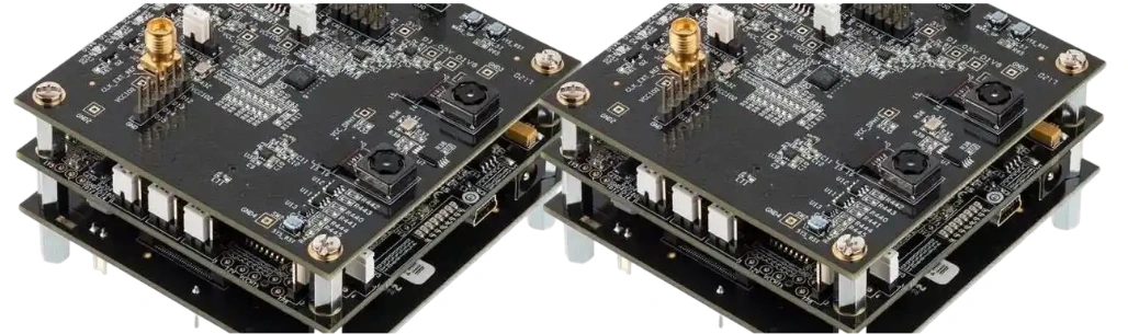
A panoramic camera PCB connects one fisheye sensor or several synchronized image sensors to processing, memory, power, networking and storage interfaces that deliver a wide-area surveillance view. A publishable “360-degree” claim requires scene coverage, image quality, stitching, latency, network and cybersecurity evidence—not only total megapixels.
Key Takeaways
- Choose single-sensor fisheye, stitched multisensor or independent multidirectional architecture from scene geometry and evidential detail.
- Multi-sensor stitching needs optical calibration, controlled overlap, synchronized frames and consistent exposure, white balance and image processing.
- Calculate sensor-link and memory bandwidth from active pixels, frame rate, bit depth and protocol overhead; nominal output resolution is not raw bandwidth.
- Route MIPI CSI-2/D-PHY or other sensor interfaces to the device-specific stackup, loss, impedance, lane and skew rules.
- Size PoE from the worst simultaneous load: sensors, SoC/NPU, DDR, Ethernet, IR, heater, storage and any motor—not average daytime power.
- Storage follows encoded bitrate and retention. At constant 16 Mbps, one stream produces about 172.8 GB per 24 hours in decimal units.
- ONVIF profile conformance, secure identity, signed updates and vulnerability support are product-level deliverables, not automatic PCB features.
Table of Contents
- Choose the Panoramic Camera Architecture
- Turn Field of View into Scene Evidence
- Synchronize and Calibrate Multiple Sensors
- Design Sensor Links, Processing and Memory
- Build the PoE and Power Architecture
- Manage Heat Without Degrading the Image
- Plan Encoding, Network and Storage
- Release Edge Analytics and Cybersecurity
- Design for Outdoor Reliability
- Use an Optics-to-Network Release Matrix
- Diagnose Common Panoramic Camera Failures
- Panoramic Camera PCB RFQ Checklist
- Reference Standards and Responsibility Boundaries
- How HILPCB Supports Camera Electronics
- FAQ
- Conclusion
Choose the Panoramic Camera Architecture
“Panoramic” describes several different products. Freeze the output views, recording format and client behavior before selecting sensors and SoC.
| Architecture | Main advantage | Main constraint | Best fit |
|---|---|---|---|
| Single fisheye sensor | Compact 180°/360° overview with no inter-sensor seam | Pixel density varies strongly across the projected scene; dewarping consumes processing | Rooms where overview matters more than distant detail |
| Stitched multisensor | Wider view with higher, more uniform pixel density | Calibration, overlap, parallax, exposure and synchronization complexity | Open areas requiring one cohesive panorama |
| Multidirectional independent sensors | Each head can aim at a different region with its own stream | Not necessarily a seamless panorama; more stream management | Intersections, corners and irregular sites |
| Panorama plus optical PTZ | Overview remains while a PTZ captures detail | Higher power, mechanics, cost and control complexity | Operators need simultaneous context and close-up evidence |
Electronic pan/tilt/zoom crops and dewarps captured pixels; it does not create optical detail that was never sampled. Record whether the VMS receives a fisheye stream, dewarped views, a stitched panorama, independent channels or several of these simultaneously.
Turn Field of View into Scene Evidence
Horizontal/vertical field of view and total resolution do not prove identification performance. Map pixel density across the installed scene after lens distortion, dewarping, cropping, overlap and stitching. A single fisheye can allocate many source pixels to the ceiling or near-field while distant targets receive too few.
The site design should define:
- mounting location, height, tilt and orientation;
- target zones, distances and required detection/observation/recognition/identification task;
- day/night illumination, glare, shadows, backlight and weather;
- minimum frame rate, motion blur and shutter constraints;
- privacy masks and regions that must never be recorded;
- blind regions caused by the camera body, walls, pillars or seam geometry.
Validate with representative targets at worst-case positions. Digital zoom on a monitor is not a substitute for sufficient scene pixels and optical focus.
Synchronize and Calibrate Multiple Sensors
Stitching aligns images only when their geometry and capture state are controlled. Each camera needs intrinsic calibration such as focal length, principal point and lens distortion, plus extrinsic position and orientation relative to the panorama.
Overlap must be large enough for robust alignment and blending but not so large that pixels and bandwidth are wasted. Objects close to the camera create parallax because each lens sees a different perspective; no homography can make every depth plane seamless. Define a minimum stitching distance and test people or vehicles crossing seams at multiple depths.
Frame synchronization should be tied to the artifact budget. Hardware trigger/frame-sync signals usually provide stronger simultaneity than software timestamps alone. Measure exposure start and readout relationship, especially with rolling-shutter sensors and moving targets. Synchronize exposure, gain, white balance, tone mapping and temporal noise reduction so a target does not change brightness or color at a seam.
Mechanical tolerance belongs in calibration control. Sensor-board location, lens thread/barrel seating, adhesive cure, focus adjustment and enclosure torque can change alignment. Store calibration data by unit or controlled module revision, protect it from corruption and define recalibration triggers.
Design Sensor Links, Processing and Memory
Estimate raw active-image payload per sensor as:
width × height × frames per second × bits per pixel
Then add sensor blanking, packet/protocol overhead and implementation margin. RAW10, RAW12, YUV and compressed streams have different payloads. Verify that the selected sensor lane configuration, receiver ports, ISP throughput and simultaneous operating modes are supported by the SoC—not merely that each component lists MIPI CSI-2.
Use the sensor, SoC and PHY reference designs to define D-PHY/C-PHY lane topology, differential impedance, loss, intra-pair and lane skew, transitions and test access. A generic “100-ohm and equal length” rule is incomplete. The production stackup, package breakout, connectors or flex cables and receiver timing budget determine acceptable geometry.
Route every high-speed lane over a continuous reference without stubs. Keep layer transitions controlled and provide return vias where required. Review crosstalk from DDR, Ethernet, clocks and switching regulators. If sensors are on separate boards, include connector/flex loss, pin field, ground continuity and assembly tolerance in the channel.
The processing chain may include sensor correction, demosaic, HDR merge, dewarping, stitching, scaling, overlays, analytics and encoding. Model memory bandwidth for concurrent reads/writes and worst active features. DDR routing, PDN impedance and package escape must follow the processor/memory topology; high PCB layer count alone does not create margin.
Build the PoE and Power Architecture
A PoE camera is a powered device (PD) that must interoperate with the intended power-sourcing equipment. Choose the IEEE 802.3 PoE type/class from the power at the PD and cable conditions, then implement detection, classification, inrush, maintain-power behavior, isolation and fault handling according to the selected PD controller and standard.
Build a mode-based power table:
| Load | Worst state to include |
|---|---|
| Sensors/clocking | Maximum resolution, frame rate and HDR mode |
| SoC/ISP/NPU | Stitching, analytics and encoding simultaneously |
| DDR/storage | Highest sustained traffic and write activity |
| Ethernet/PoE conversion | Cable/input range and converter losses |
| Illumination | IR LEDs at maximum allowed duty and temperature |
| Environment | Heater, defogger or fan startup |
| Mechanics | PTZ, filter or shutter actuation if fitted |
Sequence sensor rails, clocks, reset and I/O to prevent back-powering. Validate transient droop when IR, heater, NPU or storage starts. Keep PoE magnetics, switching nodes and common-mode currents away from sensor clocks and analog rails. Surge, ESD, isolation and earthing must be designed for the installation and regulatory environment.
Manage Heat Without Degrading the Image
Thermal design protects both silicon and evidence quality. Image-sensor dark current and noise change with temperature; lens/barrel dimensions can shift focus; SoC/NPU and DDR can throttle or become unstable.
Create a power map for every operating mode and a thermal-resistance path from junctions through PCB, interface material and enclosure to ambient. Thermal vias and copper spreading help only when they connect to an effective sink. Keep SoC and PoE heat away from sensors where practical, and avoid heating one sensor more than its neighbors because seam color/noise can diverge.
Measure steady-state and transient temperatures in sealed, sun-loaded, still-air and low-temperature startup conditions as applicable. Run full analytics, encoding, IR and network traffic while measuring image noise, focus, frame drops and throttling—not temperature alone.
Plan Encoding, Network and Storage
H.264 or H.265 can reduce network/storage load, but bitrate depends on resolution, frame rate, scene motion/detail, noise, GOP, rate control and image settings. Low-light noise or rain can increase variable bitrate and reduce compression efficiency.
For constant bitrate, approximate decimal storage as:
GB/day = bitrate in Mbps × 10.8
Thus 16 Mbps is about 172.8 GB/day, 5.184 TB for 30 days or 15.552 TB for 90 days before filesystem, redundancy, metadata, audio and retention overhead. Multiple independent or dewarped streams add their own bitrates. Event recording changes the calculation only if event frequency and pre/post-roll are measured realistically.
Create a network budget for peak stream bitrate, multicast/unicast clients, firmware downloads, metadata, retransmission and switch uplinks. Validate latency and loss from camera to VMS/NVR under congestion. A local microSD card, if used, needs endurance, filesystem recovery and removal/fault tests.
ONVIF Profile T can support advanced IP video streaming features, while Profile M addresses analytics metadata and events. Only a registered conformant product and the specific supported profile/features provide interoperability evidence; an ONVIF library in the BOM does not.
Release Edge Analytics and Cybersecurity
Analytics require scene-specific evidence. Define classes, zones, minimum target size, occlusion, lighting, crowd density, weather, false-positive/negative limits and model version. A stitched seam can distort objects or duplicate detections, so compare analytics before and after stitching and track objects across sensor boundaries.
Treat every camera as a networked computer. The release baseline should include:
- unique device identity and no universal default password;
- authenticated roles, least privilege and secure credential reset;
- protected data/configuration in transit and at rest as required;
- verified boot and signed, rollback-controlled updates;
- disabled or documented services, ports and debug interfaces;
- security logging, time integrity and tamper/factory-reset behavior;
- component inventory, vulnerability intake and supported update lifetime.
Privacy masks must survive reboot, profile change, dewarping and firmware update and must apply to every exported stream or snapshot required by the product. Face or license-plate analytics can create additional legal and biometric-data obligations.
Design for Outdoor Reliability
Ingress protection is an enclosure result under IEC 60529, not a PCB material claim. Control gaskets, cable glands, lens seals, vents, pressure cycling, water paths and condensation. Conformal coating can reduce contamination risk but does not make a board waterproof, and it complicates connectors, optics, rework and heat transfer.
Qualification should reflect the installation: temperature/humidity cycling, powered condensation, UV and corrosion exposure where relevant, vibration/shock, cable surge/ESD, PoE brownout, long-duration recording and repeated thermal cycling. A high-Tg laminate or ENIG finish may suit a design but does not by itself prove outdoor service life.
Use an Optics-to-Network Release Matrix
This matrix prevents a team from passing the PCB while the surveillance evidence fails elsewhere.
| Release gate | Controlled inputs | Required evidence | Reject when |
|---|---|---|---|
| Scene/optics | Mounting, FOV, target zones, lenses, illumination and privacy | Pixel-density map plus day/night target captures | Required detail or masked region is not achieved |
| Sensor module | Focus, calibration, frame sync, exposure/color and mechanics | Seam crossing, parallax, motion and unit-to-unit data | Calibration changes after normal assembly |
| PCB/channel | Stackup, sensor lanes, clocks, DDR, PDN and test access | SI/PI review plus stress-mode error counters | Link margin depends on one cable/temperature/unit |
| Processing | ISP, stitching, encoding and analytics versions | Frame-drop, latency, seam and detection results | Features cannot run simultaneously within budget |
| Power/thermal | PoE class, IR/heater/motor modes, enclosure and ambient | Startup/transient plus worst-mode thermal/image data | Droop, throttling, focus or image-noise limit fails |
| Network/security | Profiles, bitrate, users, updates, VMS/NVR and retention | Interoperability, storage, penetration and recovery tests | Unsupported service, stale credential or lost evidence appears |
| Pilot/change | Released BOM, calibration, firmware/model and process | Yield, traceability and targeted requalification | Change invalidates optical, electrical or security evidence |
Diagnose Common Panoramic Camera Failures
| Symptom | Likely causes | Next discriminating test |
|---|---|---|
| Moving person splits or doubles at seam | Unsynchronized exposure, parallax or bad calibration | Cross seams at several distances with frame timestamps logged |
| Seam color changes after warm-up | Sensor temperature gradient or independent auto-exposure/white balance | Log sensor temperature and fixed/manual imaging settings |
| MIPI errors appear only with IR on | Rail/ground transient, EMI or thermal shift | Correlate error counters with IR current and probe PDN |
| 360° overview lacks usable detail | Pixel density diluted by projection/cropping or poor focus | Map target pixels across installed scene |
| VMS sees video but not analytics | Wrong ONVIF profile/metadata implementation or client feature gap | Verify registered profile and inspect negotiated metadata |
| Storage exceeds estimate | VBR scene complexity, noise, extra streams/audio or overhead | Record actual peak/average bitrate over representative days |
| Outdoor image fogs after temperature change | Condensation, seal/vent or heater control failure | Powered humidity/temperature cycle with enclosure inspection |
Panoramic Camera PCB RFQ Checklist
Optics/sensors: architecture, sensor/lens parts, module CAD, FOV, overlap, frame sync, calibration method/data, focus process, output modes, day/night/IR and target-zone requirements.
PCB/compute: schematic, Gerber/ODB++/IPC-2581, stackup, MIPI/DDR constraints, SoC/ISP/NPU, memory/storage, clocks, PDN, connectors/flex, test points, programming and secure key provisioning.
Power/mechanics: PoE type/class and controller, mode power table, IR/heater/fan/PTZ, surge/isolation, enclosure thermal model, gaskets/vents, ambient, ingress target and mounting.
Network/release: codecs, streams, bitrate/latency, ONVIF profiles, VMS/NVR, analytics/metadata, retention, cybersecurity baseline, update lifetime, fixtures, calibration traceability, acceptance limits and change triggers.
Reference Standards and Responsibility Boundaries
- IEC 62676-4 — IEC
- IEEE 802.3 — IEEE
- ONVIF Profile T — ONVIF
- ONVIF Profile M — ONVIF
- IEC 62368-1 — IEC
- IEC 60529 — IEC
- ETSI EN 303 645 — ETSI
- NISTIR 8259A — NIST
- IPC-2221 — IPC
- IPC-6012 — IPC
- IPC-A-610 — IPC
Applicable surveillance, privacy, radio, EMC, safety, cybersecurity and installation rules vary by market and deployment. HILPCB can fabricate and assemble released camera electronics and support DFM and test access. The product owner remains responsible for optics, image quality, calibration/stitching, algorithms, PoE/Ethernet conformance, security lifecycle, privacy, enclosure ingress, system integration and final certification.
How HILPCB Supports Camera Electronics
HILPCB can review sensor/SoC breakout, production stackup, high-speed reference continuity, DDR/MIPI escape, PDN, PoE spacing, thermal-via structures, calibration access and assembly keep-outs. High-speed PCB manufacturing supports controlled camera and memory channels, while HDI PCB manufacturing can help dense sensor and BGA fan-out when justified by the stackup and reliability plan.
For integrated builds, turnkey PCB assembly can maintain released sensor, lens/module, memory and security-component revisions plus programming requirements. Exact optical calibration, secure provisioning, coating, environmental and functional-test scope must be defined and confirmed per quotation.
FAQ
Is one fisheye sensor or several sensors better for a panoramic camera?
A fisheye is compact and avoids stitching seams but has uneven scene pixel density. Multiple sensors can provide more detail and flexible coverage but require synchronization, calibration, overlap and blending. Choose from the installed scene and evidence task.
Does total megapixel count prove panoramic surveillance detail?
No. Useful detail depends on lens, projection, dewarping/cropping, overlap, focus, target distance, lighting and motion. Validate pixel density and representative targets across every required zone.
How much storage does a 16 Mbps panoramic stream need?
At continuous constant bitrate, about 172.8 GB per day or 5.184 TB per 30 days in decimal units. Add filesystem, redundancy, metadata, audio and any extra streams; actual VBR footage must be measured in representative scenes.
Does ONVIF support mean every VMS feature will work?
No. Interoperability depends on registered product conformance to the relevant profile and the optional features supported by both camera and client. Test streaming, imaging, events, metadata, audio, users and recovery with the target VMS.
Conclusion
A panoramic camera PCB succeeds only when scene detail survives the full chain from lenses and synchronized sensors through stitching, encoding, PoE, network and storage. Freeze that chain as a measurable release contract, then validate worst simultaneous operating modes and security lifecycle. Send HILPCB the sensor architecture, stackup, compute/power design, mechanics and manufacturing test requirements for DFM and assembly quotation review.