
Decision: Select a specific one-time fuse only after the product engineer has defined the protected path and reviewed fault, thermal, assembly and validation evidence. Treat each proposed replacement as a separate engineering decision.
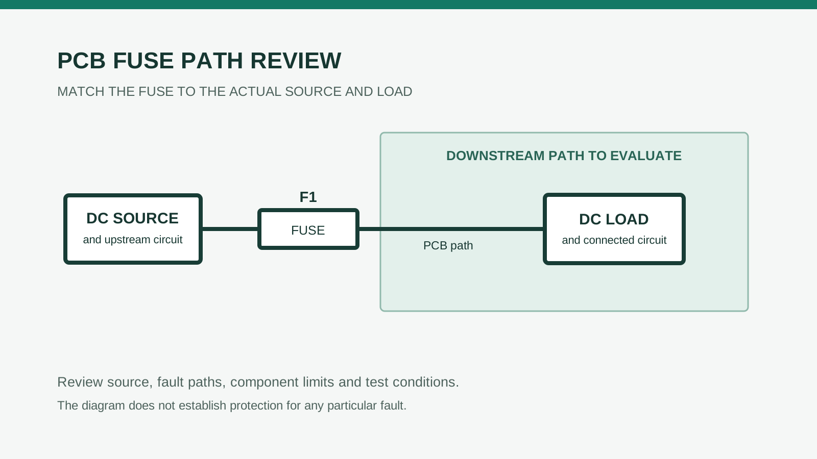
The protected path in this example runs from the external supply connector, through fuse F1 and the board’s downstream copper and connector, to a DC load. The design objective is to limit damage from specified downstream overcurrents while coordinating with the source and upstream protection. F1 cannot be assumed to protect every upstream wire, the source itself, or every possible load failure.
This is a release method, not an assertion that any part is suitable for a particular product. The operating currents, fault-source characteristics, board construction and damage limits remain to be supplied by the product team.
The decision record starts at F1
A fuse selection is incomplete until the team can answer two questions:
- What event must F1 tolerate without opening?
- What event must F1 interrupt before an allocated damage or safety limit is exceeded?
Those questions can conflict. A fuse that survives repeated startup pulses may also allow more energy into a fault. Conversely, a part that responds quickly to an overload may open during legitimate startup.
For the example path, the release owner should define:
- The external source, its normal voltage range, maximum voltage and stored energy.
- The upstream wiring and protection, including which portions F1 does not protect.
- Connector contacts, PCB traces, vias and downstream wiring through which fault current flows.
- Load operating modes, including maximum continuous current and startup current.
- Credible downstream overload and short-circuit locations, including faults that are not close to the fuse.
- Damage and safety limits for the source, conductors, connectors and load, plus the assumptions behind those limits.
Also examine faults on the source side of F1 and any downstream energy sources, such as charged capacitors or another connected supply. F1 may not interrupt their contribution in the desired direction. If protection depends on an upstream device, document that device and its coordination rather than attributing its job to F1.
Start with the exact manufacturer's data
Record the complete manufacturer part number and controlled datasheet revision. Check current rating, applicable AC or DC voltage rating, interrupting rating, time-current characteristics, pulse behavior, temperature derating and assembly limits for that exact item. Littelfuse's 440 Series 1206 High I²t Fuse datasheet, revision 30 May 2024, illustrates why ratings and conditions vary by current rating. Check the current documentation before selecting a part. No particular fuse has been approved for the hypothetical circuit here.
A fault-current comparison—not a protection verdict
Assume, purely for arithmetic, that an engineering analysis of the hypothetical DC path establishes all of the following:
- Maximum circuit voltage at F1 is 16 V DC.
- The maximum prospective fault current at F1 is 40 A DC.
- The analyzed source and test conditions are applicable to the manufacturer’s stated interrupting rating.
Assume the candidate fuse has an interrupting rating of 50 A at 32 V DC under applicable conditions. Both the part rating and the circuit values in this example are hypothetical. The comparison is:
40 A prospective fault current ≤ 50 A interrupting rating, with the assumed 16 V DC below the 32 V DC voltage rating.
That passes only this simplified numerical comparison. It does not establish that the assumed 40 A is correct, that the fuse clears every credible fault safely, or that the traces, connector, source and load remain within their limits. The analysis must account for source tolerance, wiring impedance, charged capacitors, parallel sources and other credible configurations. The engineering owner must assess whether the manufacturer's interrupting test conditions, including the DC circuit time constant where applicable, are relevant to the actual fault. The analysis should also identify lower-current faults that may persist longer than a high-current short.
Turn the comparison into a project record
The numbers above demonstrate one comparison, not a completed release. The following example fields show what the design team still needs to supply for this fictional F1 path:
| Item | Example record | Evidence still needed |
|---|---|---|
| Maximum voltage and prospective fault at F1 | Assumed 16 V DC and 40 A DC | Source configurations, impedance, stored energy and applicable fault analysis |
| Lower-current fault | Not supplied | Credible fault locations, current range and expected duration |
| Startup pulse | Not supplied | Measured or justified waveform, repetition, temperature and cooling conditions |
| Protected path limits | Not supplied | Allowable conductor, connector and load limits under applicable fault conditions |
| Primary and alternate fuse | No actual MPN selected; alternate pending | Exact part documents, condition-matched comparison and project approval |
Keep the unfilled entries open until the responsible engineer supplies evidence. For example, a component substitution approval record can track the proposed alternate and its approval scope; it cannot by itself validate fuse protection.
This example is not an instruction or authorization to create a short circuit. Destructive fault tests require qualified personnel and an approved test plan with appropriate equipment, containment and safety controls.
Read time-current and I²t evidence together
Littelfuse’s Fuseology explains that the illustrated time-current curves represent average melting behavior and are design aids rather than fuse specifications. Use a curve to investigate likely behavior and select cases for further evaluation; do not treat a single plotted line as a guaranteed clearing boundary. Obtain applicable tolerances or additional manufacturer information when a protection decision needs limits the datasheet does not provide.
Melting is not the same as clearing. The element first melts; an arc can then conduct before current is fully interrupted. Total clearing I²t includes both the melting and arcing portions. A published nominal melting I²t is not automatically the total clearing I²t; I²t alone also does not establish energy dissipated in a downstream trace or load.
For startup, capture the actual current waveform rather than only a peak value. Record pulse shape, duration, repetition count, interval, initial temperature and cooling conditions. The pulse integral, ∫I²dt over the defined pulse interval, can support comparison with manufacturer guidance, but simply finding it below the nominal melting I²t does not establish lifetime pulse withstand. Repeated pulses can change the result, and the selected manufacturer must be consulted when its data does not cover the actual pulse conditions.
An NTC inrush limiter can affect startup current in some circuits, but its hot and restart behavior must be considered in the actual design. It does not replace the fuse's fault-coordination review.
For fault coordination, the engineering owner needs suitable clearing behavior or other evidence at the actual circuit conditions, then must compare the outcome with the limits allocated to the protected path. A nominal fuse value alone cannot complete that comparison.
Control the alternative as a separate design decision
An alternative with the same package and current rating is not automatically interchangeable. Compare the complete manufacturer documentation for voltage and interrupting ratings, time-current characteristics, pulse withstand, resistance, temperature derating, footprint, assembly limits and application restrictions. Document the effect on the protected path and repeat the validation required by the product's change-control plan. A PPTC or electronic fuse has different behavior and is not an automatic replacement for a one-time fuse.
Release the assembly interface, not just the BOM line
The electrical review can be invalidated by an uncontrolled board or assembly change. For each approved MPN, the manufacturing package should identify the land pattern, solder paste process, permitted thermal profile, inspection requirements and traceability method.
Use the exact selected part’s datasheet for its applicable soldering and handling conditions. Do not transfer one family’s limits to another.
The release record should connect the approved footprint and profile to the actual assembly revision. It should also specify:
- Fuse location and nearby heat-source constraints.
- Reel and full MPN identification at receiving and line setup.
- Applicable moisture and packaging controls.
- Inspection criteria for the correct part, placement and solder joints.
- Limits on rework and the replacement method after an opened fuse.
Continuity can detect some opens or assembly errors, but continuity is not proof of fault clearing. A fuse that conducts in a low-current check has not thereby demonstrated its interrupting capacity, overload response or pulse life.
After an in-service opening, the responsible service procedure should call for fault investigation before replacement. Do not bypass the fuse or fit a higher-current part without an approved engineering change.
Original release evidence matrix
The following matrix is a template for the hypothetical F1 decision. “Open” means the example supplies no project evidence; it does not imply a failed part.
| Decision gate | Evidence to attach | Owner | Example status |
|---|---|---|---|
| Path boundary | Schematic and annotated source-to-load path; upstream protection and downstream energy sources | Product electrical engineer | Open |
| Normal operation | Maximum load current, voltage range, operating modes and current measurement conditions | Product electrical engineer | Open |
| Startup survival | Waveforms, repetition and cooling assumptions; pulse assessment and validation report | Electrical engineer and validation lead | Open |
| Fault coordination | Prospective maximum and credible lower fault cases; conductor and load limits; source assumptions | Safety/design authority | Open |
| Primary MPN | Exact primary MPN, datasheet revision, rating review and application restrictions | Component engineer | Candidate only |
| Alternative MPN | Exact alternative MPN, comparison, change assessment and part-specific validation | Component engineer and design authority | Pending; not interchangeable by default |
| Board and assembly | Approved layout, footprint, thermal profile, work instructions and inspection plan | PCB designer and manufacturing engineer | Open |
| Product validation | Approved test plan, sample rationale, results, deviations and disposition | Validation lead | Open |
| Compliance and release | Applicable product requirements, evidence review, BOM revision and sign-off | Product compliance owner and release authority | Open |
A destructive test plan should define the configuration, source limits, fault locations, instrumentation, acceptance criteria, sample plan and post-test inspection before testing begins. Testing should cover relevant assembled configurations, including the alternative if it is to be approved. Engineering must disposition failures and decide whether a design, assumption or test plan needs revision.
Component recognition is evidence about the component under its applicable recognition conditions; it is not certification of the assembled PCB or finished product. The product compliance owner must determine the applicable product-level route and evidence.
An assembly inspection report can document the agreed inspection scope, results and exceptions; it does not establish fault-clearing performance. For adjacent component context, see circuit board components.
For PCB assembly, include the approved fuse MPN and alternatives, BOM, board files, part-specific assembly limits, inspection criteria and any requested test requirements when you request a quote. Agree the assembly and testing scope for the order; electrical design, fault coordination and product certification remain subject to the responsible project's requirements.
Release checklist with ownership
- Product electrical engineer: Identify the protected path, source configurations, normal current and inrush waveform.
- Safety/design authority: Establish fault cases, protected-element limits and coordination with upstream protection.
- Component engineer: Control the full primary MPN, datasheet revision and application restrictions; hold the alternative pending approval.
- PCB designer: Release the footprint, current path and thermal context tied to the board revision.
- Manufacturing engineer: Approve part-specific assembly, inspection, traceability and rework instructions.
- Validation lead: Obtain an approved plan and arrange qualified personnel for any destructive testing; retain results and deviations.
- Product compliance owner: Review component evidence against applicable finished-product requirements.
- Release authority: Approve the BOM and documented alternatives only after open evidence items are resolved.
- Service owner: Document fault investigation and authorized replacement without bypassing or unauthorized uprating.
FAQ
Does a 2 A fuse open as soon as current exceeds 2 A?
No. Its response depends on current magnitude, duration, temperature and construction. Use the exact part’s specified characteristics and supporting application evidence.
Is a 50 A interrupting rating the same as a 50 A trip current?
No. The interrupting rating concerns the maximum prospective fault current the manufacturer states the fuse can safely interrupt under its rated conditions. It is not the current at which the fuse begins to melt.
Can another fuse with the same current rating replace the selected part automatically?
No. Parts can differ in resistance, melting I²t and overload characteristics, among other details. The candidate stays pending until the project approves its comparison, assembly interface and validation.
Does a continuity check confirm the fuse will protect the board?
No. Continuity is useful for detecting an open path, but it does not demonstrate fault interruption or coordination with the protected conductors and load.
Does a recognized fuse make the finished product certified?
No. Component recognition does not by itself certify the PCB assembly or finished product. The product owner must address the applicable product-level requirements and evidence.