
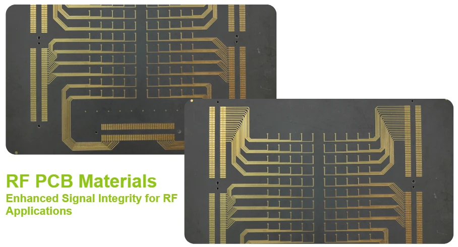
Material selection makes or breaks RF PCB performance. While standard FR4 works adequately for digital circuits, RF applications demand substrates with precisely controlled dielectric properties and minimal signal loss. The wrong material choice can turn an excellent circuit design into an expensive failure.
At Highleap PCB Factory, we've learned that successful RF material selection requires balancing electrical performance, thermal management, mechanical reliability, and cost considerations. No single material excels in all areas, making the selection process both critical and challenging.
Understanding RF Material Properties
RF materials differ fundamentally from standard PCB substrates in their electromagnetic behavior. Two key parameters dominate RF material performance: dielectric constant (Dk) and dissipation factor (Df).
Dielectric Constant (Dk) determines signal propagation speed and characteristic impedance. Lower Dk values allow faster signal propagation and enable wider traces for a given impedance target. Most RF applications use materials with Dk values between 2.2 and 4.5, compared to FR4's Dk of approximately 4.4.
Dissipation Factor (Df) quantifies how much RF energy the material absorbs and converts to heat. Lower Df values preserve signal integrity over longer distances and through multiple circuit elements. Premium RF materials achieve Df values below 0.002, while standard materials typically exceed 0.010.
Temperature stability becomes crucial for applications experiencing wide temperature swings. The temperature coefficient of Dk (TCDk) indicates how much the dielectric constant changes with temperature. Materials with low TCDk maintain consistent electrical performance across temperature variations.
Moisture absorption affects both electrical and mechanical properties. PTFE-based materials typically absorb less than 0.1% moisture, while standard materials may absorb several percent, significantly altering their dielectric properties.
Rogers Materials Portfolio
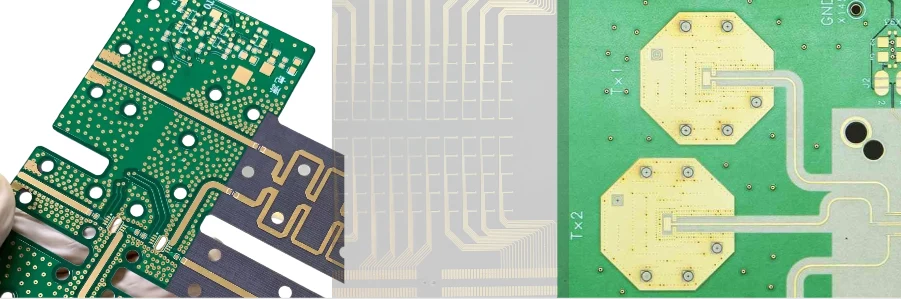
Rogers Corporation dominates the RF materials market with three main product families, each optimized for different application requirements. For a side-by-side look at RO4003C, RO4350B, and RO5880, see the Rogers substrate comparison.
RO4000 Series materials balance performance with manufacturability. RO4350B, the most popular variant, offers a Dk of 3.38 and Df of 0.0037 while remaining compatible with standard PCB processing equipment. This compatibility reduces manufacturing costs and improves yield compared to pure PTFE materials.
RO3000 Series materials target ultra-low loss applications. RO3003 achieves a Df of only 0.0013, making it ideal for precision oscillators, low-noise amplifiers, and test equipment where signal purity is paramount. The tight Dk tolerance (±0.04) ensures consistent impedance control across panels and production lots.
RT/duroid 5800 Series materials provide the ultimate in electrical performance. RT/duroid 5880 combines a Dk of 2.20 with a Df of 0.0009, delivering exceptional performance for aerospace, military, and test applications. The low Dk enables wide trace widths for easier manufacturing while maintaining 50-ohm impedance.
Material Selection Quick Reference
RO4350B / Taconic RF-35
General RF applications
RO3003 / TLY-5
Precision circuits
RT/duroid 5880
Aerospace/Military
Alternative Material Suppliers
While Rogers dominates premium RF applications, other suppliers offer compelling alternatives for specific requirements or cost-sensitive applications.
Taconic Advanced Dielectric Division specializes in PTFE-based materials with ceramic fillers. Their TLY series matches Rogers' performance while offering different mechanical and thermal properties. TLY-5A provides ultra-low loss (Df = 0.0009) with excellent dimensional stability.
Isola Group offers thermoset alternatives to PTFE materials. I-Tera MT40 achieves good RF performance (Dk = 3.45, Df = 0.0031) while maintaining FR4-like processing characteristics. This combination enables significant cost savings in applications where ultimate performance isn't required. More detail on these laminates is in our Isola PCB article.
Panasonic Megtron materials target high-speed digital applications but work well for lower-frequency RF circuits. Megtron 6 offers improved loss characteristics compared to standard FR4 while maintaining compatibility with standard processing equipment.
Each supplier offers unique advantages. Rogers provides the broadest product line and most application support. Taconic excels in specialized applications requiring specific mechanical properties. Isola focuses on cost-effective alternatives for volume applications.
Application-Specific Material Recommendations
5G Infrastructure
Sub-6GHz: RO4350B
mmWave: RO3003/RT5880
Automotive Radar
AEC-Q100 qualified
-40°C to +125°C range
Aerospace & Defense
Space-qualified materials
Full traceability required
IoT & Consumer
Cost-optimized hybrids
Enhanced FR4 blends
Match material properties to application needs — avoid over-specifying.
Cost Optimization Strategies
RF materials are much more expensive than standard PCB substrates, making cost optimization crucial for commercial success. One effective approach is using hybrid stack-ups, where premium RF materials are reserved for layers carrying critical RF signals, while standard materials are used for power, ground, and digital control layers. This strategy can reduce material costs by 40-60% without compromising RF performance. Additionally, material thickness optimization by using standard thicknesses can further cut costs and lead times, avoiding the need for custom processing charges.
Another key strategy is improving panel utilization efficiency. By optimizing board dimensions, you can maximize the number of circuits per panel, reducing material waste and lowering per-unit costs. Volume planning also plays a significant role in cost savings. Long-term supply agreements with material suppliers can secure better pricing through volume discounts, but this requires careful demand forecasting and inventory management to ensure accuracy and avoid overstocking.
RF PCB Materials and Manufacturing Considerations
When designing RF PCBs, selecting the right materials is crucial for achieving high performance. However, certain RF PCB materials may not always be in stock, which can lead to delays. It’s essential to check with suppliers early in the design phase to confirm material availability or ask PCB manufacturers to provide layer stack-ups in advance. This helps avoid unexpected procurement cycles when your project is ready for production.
RF materials require specialized processing techniques that differ from standard FR4 handling. For example, PTFE materials, often used in high-frequency designs, need different approaches for drilling, cleaning, and plating. Their chemically inert nature requires plasma treatment or chemical etching to ensure proper adhesion. Using specialized drill bits and controlled parameters is crucial to avoid delamination during via formation.
Manufacturing RF PCBs with these materials demands precise layer registration, especially since RF materials have tighter impedance requirements. Maintaining registration accuracy within ±0.025mm (±1 mil) ensures impedance tolerances are met. Additionally, the thermal properties of RF materials differ from FR4, requiring optimized lamination parameters to prevent delamination and ensure proper bonding. Quality control involves enhanced testing procedures, including incoming material inspection, process monitoring, and final electrical testing to maintain consistent performance and reliability. HILPCB applies these controls when building Rogers PCBs on RO4000 and RT/duroid laminates.
Expert Material Selection
Get personalized RF material recommendations for your specific application
FAQ
Which material parameters matter most when selecting an RF PCB laminate?
The most important parameters are dielectric constant stability, dissipation factor, thickness tolerance, copper roughness compatibility, and thermal-mechanical behavior. Frequency range, trace geometry, and the required insertion-loss budget should drive the decision rather than choosing a brand by default.
Is Rogers always the right answer for RF PCB materials?
No. Rogers is widely used because it has a broad portfolio and strong application history, but Taconic, Isola, Panasonic Megtron, and other suppliers may be a better fit depending on frequency, cost target, mechanical needs, and factory process compatibility. The correct choice is application-specific, not brand-specific.
How can teams reduce RF material cost without hurting performance?
A common approach is to use hybrid stack-ups, keeping premium RF laminates only on the signal layers that truly need them while using lower-cost materials elsewhere. Teams also reduce cost by avoiding over-specification, staying with standard thicknesses, improving panel utilization, and confirming supply-chain availability early.
Why does manufacturing capability matter as much as the laminate datasheet?
Because RF performance depends on how the material is processed, not just on nominal Dk and Df values. Drilling, plasma treatment, copper roughness, registration accuracy, lamination control, and impedance verification all affect whether the finished board actually matches the design assumptions.
Related Topics: RF PCB Impedance Control | Microwave PCB | RF PCB Manufacturing