
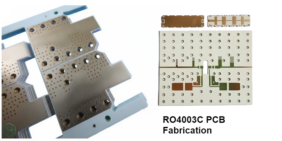
When it comes to high-frequency applications, RO4003C PCB fabrication is a popular choice due to its low loss and stable dielectric properties. This material is ideal for RF, microwave, and high-speed digital designs, offering a significant performance advantage over standard FR-4. However, RO4003C PCB fabrication is just one element in a larger design process that often requires a mix of different PCB types. Engineers frequently need to integrate RO4003C with other PCBs, such as digital, power, or backplane boards, to achieve the desired functionality and reliability in complex systems.
At HILPCB, we have the capability to produce virtually all types of PCBs, not just high-frequency ones like RO4003C. Whether you need HDI, rigid-flex, multi-layer, or other specialized boards, our extensive manufacturing expertise ensures we can meet the diverse needs of your projects while delivering high-quality, reliable results every time.
1. Positioning RO4003C Among Rogers High-Frequency Laminates
A useful way to think about RO4003C PCB fabrication is to see it as part of a material “toolbox”, not a single fixed answer. Rogers divides many of its RF and microwave laminates into three major families that frequently appear together in the same product line.
1.1 RO4000 Series – Cost-Effective and Manufacturable
For many radio platforms, RO4000™ series laminates are the starting point because they balance RF performance and manufacturability.
Common materials include:
- RO4003C – the workhorse for a wide range of RF front-ends and high-speed traces
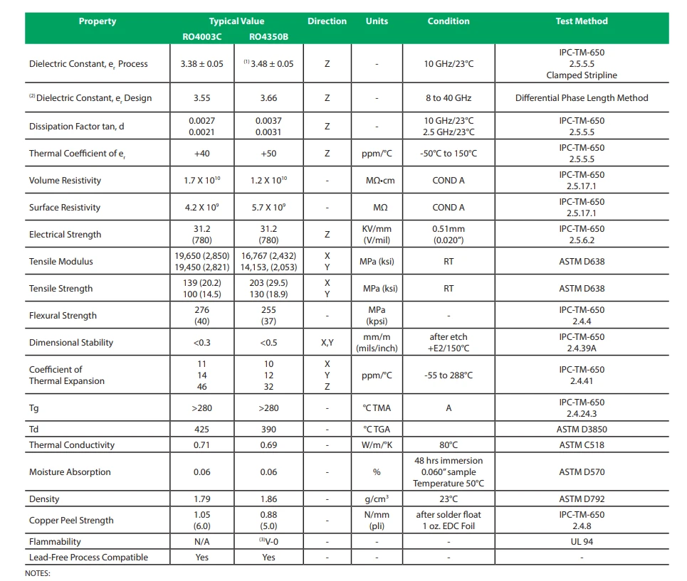
- RO4350B – similar application space, with slightly different electrical and thermal properties
- RO4360G2 – higher Dk for more compact circuits and smaller RF components
- RO4835 – improved oxidation stability for demanding environments
- RO4725JXR / RO4730G3 – antenna-grade materials optimized for low PIM and specific frequency ranges
In this family, RO4003C PCB fabrication often covers:
- Microstrip and stripline RF paths up to several GHz
- Mixed-signal boards where only part of the circuitry demands low loss
- Prototypes and derived variants that sit on the same mechanical platform as the main product
At HILPCB, these materials are grouped within our high-frequency PCB and Rogers PCB services. RO4003C is frequently combined with FR-4 in hybrid stackups when only some layers require RF-grade performance.
1.2 RO3000 Series – Higher Performance, Lower Loss
For designs with stricter link budgets or higher operating frequencies, the RO3000™ series becomes relevant:
- RO3003, RO3006, RO3010 – different Dk options for compact, predictable RF structures
- RO3035 – mid-Dk material for specific filter and antenna topologies
- RO3203 / RO3206 / RO3210 – glass-reinforced versions with robust mechanical performance
In many product families, a first generation may be built primarily on RO4003C, with later high-performance variants migrating critical functions onto RO3000 materials while keeping mechanics and interfaces similar. HILPCB supports this progression so that RO4003C circuit board fabrication and RO3000-based PCBs share as much design and process know-how as possible.
1.3 RT/duroid Series – Ultra-Low-Loss and High-End RF
At the top end of RF performance, RT/duroid® laminates are used in very low-loss or very high-frequency applications:
- RT/duroid 5870 / 5880 – ultra-low-loss materials used in many microwave and mmWave systems
- RT/duroid 6002 / 6202PR – stable, low-loss materials suited to phased arrays and mission-critical applications
- RT/duroid 6035HTC – high thermal conductivity for power-dense RF designs
These are less likely to replace RO4003C throughout a system but may appear in specific modules—precision filters, oscillators or antenna feeds—next to a broader framework of RO4000 and FR-4 boards. HILPCB treats RT/duroid and RO3000 as natural extensions of a RO4003C-based platform, not as completely separate worlds.
2. Where RO4003C PCB Fabrication Fits in a Real Product
A working RF or high-speed product usually needs more than one printed circuit board. RO4003C often plays a central RF role, while other laminates and board types complete the system.
2.1 RF Front-Ends and Mixed-Signal Cores
Typical functions placed directly on RO4003C include:
- RF front-end chains: LNA, PA, mixers, filters, couplers, splitters, baluns
- Controlled-impedance high-speed links that share a board with RF sections
- Sensitive analog circuits that benefit from low, stable Dk and low loss
For these functions, RO4003C circuit board fabrication aims to give designers predictable impedance and manageable loss, while still using a production flow compatible with volume manufacturing.
HILPCB can implement these RF cores as stand-alone modules or as parts of larger multilayer PCBs with both RO4003C and FR-4 layers.
2.2 Companion PCBs: Digital, Power and Backplanes
Most products also include several non-RF boards that must align mechanically and electrically with the RO4003C PCB:
- Digital control boards – FR-4 or high-Tg multilayers hosting MCUs, FPGAs, processors, memories and digital interfaces
- Power and driver boards – thicker copper PCBs, sometimes with thermal vias or even metal-core structures for high-power devices
- Backplanes or motherboards – high-layer-count boards that distribute power, clocks and data between plug-in RF modules
- Front-panel and interface PCBs – user interface, status LEDs, low-frequency interfaces, often on cost-optimized FR-4
HILPCB fabricates these companion boards within the same project as the RO4003C RF core, so that:
- Connector footprints and stackups are coordinated across the whole system
- Mechanical envelopes and mounting patterns are consistent
- Assembly and test strategies cover the full set of boards, not just the RF section
This “board set” approach typically reduces the need to manage multiple PCB vendors for a single product.
2.3 Rigid-Flex, Flex and Special-Purpose PCBs
Compact and mechanically complex devices often require more than simple rigid boards:
- Rigid-flex PCBs connecting RO4003C RF sections to other boards in tight spaces
- Flex jumpers between RF modules and antennas or front panels
- Metal-core PCBs for LED drivers or RF power stages that generate significant heat
HILPCB can add these as part of the same build package that includes RO4003C PCB fabrication, which simplifies mechanical integration and ensures that impedance, bend radius and assembly constraints are considered together.
3. Using RO4003C Together with Other Rogers Laminates
Because HILPCB supports the full set of laminates you listed, engineers can think in terms of “placing the right material in the right location” rather than forcing a single choice everywhere.
3.1 Typical Material Allocation Patterns
Some common patterns we see in practice:
RO4003C + FR-4 hybrid boards RF and selected high-speed layers on RO4003C; low-speed digital and power on FR-4.
RO4003C for general RF + RO3000 for critical paths Most RF routing on RO4003C; specific filters or resonators using RO3003 or RO3010 on separate boards or sub-areas.
RO4000 for main platform + RT/duroid submodules Main radio or radar board on RO4003C / RO4350B; ultra-low-loss structures on RT/duroid 5880 or 6035HTC, possibly as small daughterboards or inserts.
HILPCB’s Rogers PCB and Teflon PCB capabilities exist specifically to support this kind of mixed material planning, with RO4003C PCB fabrication as a frequent anchor point.
3.2 Product Families and Platform Reuse
Many companies build product families on a common mechanical and electrical platform:
- Entry or mid-range variants use mainly RO4003C and FR-4
- High-end variants upgrade selected sections to RO3000 or RT/duroid, keeping connectors and mechanics compatible
- Future derivatives reuse the same backplane or mainboard while revising only individual RF modules
Because HILPCB fabricates and assembles all of these variants, we can maintain consistent stackup documentation and assembly processes across the entire family, even as the mix of materials changes.
4. Beyond the Bare Board: Assembly and System-Level Support
Engineers who care about RO4003C PCB fabrication normally also care about how that RF board will be assembled, tested and integrated.
4.1 Board-Level Assembly for RO4003C and Companion PCBs
HILPCB’s assembly capabilities are designed to handle both high-frequency boards and their supporting PCBs:
- SMT lines for fine-pitch RF ICs, BGAs and high-density digital components
- Placement of RF connectors, shield frames and lids, and precision coax launches
- Process windows tuned for mixed RO4003C/FR-4 or RO4000/RO3000 stacks
- AOI and X-ray inspection where appropriate
For early hardware iterations and evaluation builds, we offer small-batch assembly; for mature designs, large-volume assembly supports ramp-up and mass production using the same underlying RO4003C PCB fabrication know-how.
4.2 Module and System Assembly
Many RF and microwave boards ultimately live inside fully assembled modules, not as bare PCBs in isolation. HILPCB extends the build scope to:
- Module-level integration with housings, heatsinks and mechanical frames
- Installation of cables, harnesses and RF absorbers or gaskets
- Final inspection and functional test based on project-specific procedures
These activities are covered under our box-build assembly and turnkey assembly services. From the perspective of the design team, this makes RO4003C PCB fabrication one part of a complete path from layout data to a verified RF or mixed-signal module.
5. Practical Project Interface: Data, Review and Variants
Instead of focusing on inner factory steps, it is often more useful to define the interface between your design team and our RO4003C PCB fabrication and assembly services.
5.1 Design Data and Review
For RO4003C and related materials, we typically work from:
- Gerber, ODB++ or IPC-2581 manufacturing data
- Stackup outlines showing which layers use RO4003C, which use FR-4 or other Rogers materials
- Key impedance requirements and RF paths (even high-level notes are useful)
Before going into production, you can run a quick visual check with our online Gerber viewer and PCB viewer, then share any constraints or preferences. HILPCB can provide feedback on realistic line/space, via styles and stackup combinations for RO4003C and its companion laminates.
5.2 Handling System Variants
In many projects, one RO4003C-based design leads to multiple variants:
- Different band options (for example, replacing one filter bank or antenna section)
- Power level variants with alternative PA modules and thermal requirements
- Region-specific interfaces or regulatory differences on the digital side
Because we manufacture the full “board set”, version control and DFM feedback are consistent across RO4003C RF boards, FR-4 logic boards, power PCBs and optional high-end RO3000/RT-duroid modules.
6. How to Plan a RO4003C-Based Board Set with HILPCB
For most projects, the practical question is not “which laminate is best on paper”, but how to build a complete, manufacturable board set around RO4003C and related materials. A simple way to structure this is:
Define where RO4003C is really needed
- Use RO4003C on RF and selected high-speed layers where controlled Dk and loss directly affect performance.
- Consider RO4350B / RO4360G2 / RO4835 / RO4725JXR / RO4730G3 when you need different Dk options, higher temperature stability or antenna-oriented properties within the same RO4000 family.
- Reserve RO3003 / RO3006 / RO3010 / RO3035 / RO3203 / RO3206 / RO3210 for performance-critical paths where lower loss or specific Dk values justify the step up to the RO3000 series.
- Use RT/duroid 5870 / 5880 / 6002 / 6202PR / 6035HTC only where ultra-low loss or special thermal behavior is essential, typically in dedicated sub-modules.
List all PCBs in the system, not just the RF card
- RO4003C or other Rogers boards for RF and microwave sections.
- FR-4 or high-Tg digital control PCBs (MCU/FPGA/SoC, interfaces, memory).
- Power and driver PCBs with higher copper weight or metal core where required.
- Backplanes / motherboards for data and power distribution.
- Rigid-flex / flex PCBs for interconnects to antennas, sensors or front panels.
Align materials, stackups and mechanics across this board set
- Match connector types, stackup thickness and impedance targets between RF modules and their carrier or backplane.
- Keep mounting holes, shielding concepts and reference planes consistent across variants (for example, RO4003C base design and higher-end RO3000/RT-duroid options).
- Decide early which boards will stay on RO4003C and which may later migrate to RO3000 or RT/duroid without changing the overall mechanical platform.
Package this into a single manufacturing and assembly flow
- Share one set of fabrication data, stackup notes and material preferences for all boards.
- Let a single factory handle RO4003C PCB fabrication, other Rogers laminates and the associated FR-4, power, backplane and rigid-flex PCBs.
- Run prototypes, small batches and volume production on the same coordinated line, with common DFM rules and test strategies.
Working in this way, RO4003C is not an isolated choice but the central material in a structured RF board platform, with clear upgrade paths into RO4000, RO3000 and RT/duroid where the application demands it. HILPCB’s role is to turn that platform into a coherent set of manufacturable PCBs and assemblies, so that RF, digital, power and mechanics can be developed and produced as one integrated system rather than as separate, loosely connected boards.