

Rogers PCB manufacturing starts with the exact laminate grade and construction, not the brand alone. Hydrocarbon-ceramic and PTFE families use different processing routes; copper profile, dielectric thickness, bonding and finished geometry affect the RF result alongside the datasheet properties.
HILPCB’s Rogers fabrication service supports RO4003C, RO4350B, RO3003 and RT/duroid routes, including reviewed hybrid Rogers/FR-4 stackups. Define the RF path, material/foil, assembly exposure and acceptance measurements before releasing a prototype or repeat build. Controlled-impedance coupons, full-channel loss and assembled-product behavior require different evidence.
What Makes Rogers PCB Different from Other Materials?
Compared with a conventional FR-4 construction, a suitable RF laminate may offer lower dielectric loss or better-controlled electrical properties for the intended channel. It does not remove conductor loss, crosstalk, discontinuities or the need for a complete thermal path.
Key selection points include:
- Electrical performance: Compare process/design Dk, Df, frequency, method, thickness and copper construction. Use the appropriate design data in the field solver; a datasheet value is not a guaranteed finished-board insertion loss.
- Thermal behavior: Review thermal conductivity, expansion, resin behavior and the actual package/TIM/sink path. A stable dielectric value does not make every laminate a heat spreader or establish a maximum device temperature.
- Environmental durability: Moisture, finish, insulation, attachment and assembly/rework exposures belong in the qualification plan. Aerospace, military or industrial end use does not follow automatically from buying a particular laminate.
HILPCB can review the material, stackup, copper and controlled features together. Record approved grades and alternatives so a substitution does not silently change the model or acceptance basis.
Applications of Rogers PCBs
Relevant applications have different reasons for selecting RF materials:
- Telecommunications: 5G infrastructure, microwave circuits and RF links need construction-specific loss, phase, power and environmental budgets.
- Aerospace: Aircraft and satellite communication or sensing RF paths may need controlled material/lot and environmental evidence; board fabrication acceptance and aircraft/system qualification remain separate.
- Medical devices: MRI RF assemblies and diagnostic/wireless modules may need defined RF geometry. An ECG acquisition board does not inherently require Rogers material; select it for the actual RF/high-speed or other demonstrated circuit need.
- Automotive: Radar and selected communication/sensor interfaces can use RF laminates. Specify the mounting environment, module/radome and program evidence rather than assuming every infotainment or sensor board needs the same grade.
HILPCB can connect these application inputs with the released fabrication and assembly package, without treating a material name as product qualification.
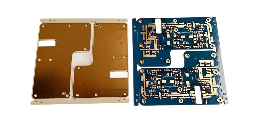
Specialized Materials for Rogers PCBs
RO3000 and RO4000 are material families, not interchangeable specifications. Select the exact grade, dielectric thickness, copper foil and bonding system.
- RO4000 hydrocarbon-ceramic routes: RO4003C/RO4350B/RO4835 can use many conventional FR-4 imaging/etch and plating operations. Bonding, drill quality and any required desmear still depend on the complete construction. Rogers’ RO4000 processing guide distinguishes those stages; it does not prescribe one press or cleaning recipe for every hybrid.
- RO3000 PTFE routes: These ceramic-filled PTFE materials need appropriate handling, bonding and drilled-hole treatment. Rogers’ RO3000/RO3200 fabrication guide separates adhesive desmear from PTFE activation before conductive seed deposition. Plasma or sodium-based activation can be used for the relevant material/process; do not transfer an RO4000 preparation rule automatically.
- Hybrid constructions: Place RF laminate where its properties are needed, with an approved FR-4/bondply combination elsewhere. Check resin flow, expansion, thickness/registration, surface preparation and assembly exposure before comparing material savings. Extra lamination or inspection work can change the economics.
HILPCB can review the grade/foil and manufacturing sequence with the RF artwork. Preserve material-lot identity, approved substitutions and the released stackup for prototype-to-production continuity.
Design Considerations for Rogers PCBs
Use the fabrication drawing and electrical model to close these decisions:
- Signal and RF paths: Specify frequency/edge conditions, routing length, phase/loss budget, references and connector/via transitions. Low Dk/Df alone does not determine the complete result; copper roughness and finish also contribute. ENIG flatness is useful for assembly but its nickel can add RF loss, so review finish and protected RF areas with the model.
- Thermal and assembly path: Supply device dissipation, package pad/net, cooling/mounting and reflow/rework limits. Review via fill/cap, solder wicking, mask and bonding rather than relying on the laminate name for heat removal.
- Finished geometry and verification: HILPCB’s Rogers route lists 75/75µm standard and reviewed 50/50µm trace/space, with ±10% standard and reviewed ±5% impedance options. Minimum feature size is not dimensional tolerance. Approve the stackup, actual finished-feature limits and coupon/TDR plan; scope any VNA S-parameters with fixture, calibration/reference plane and acceptance limits.
The Impedance Calculator can support an initial geometry estimate, while the Gerber Viewer helps inspect exported artwork. Confirm the calculation assumptions and manufacturing data with engineering; a preview does not validate the complete RF channel or assembled product.
Why Choose HilPCB PCB Factory for Your Rogers PCB Needs?
HILPCB offers material/construction review, compatible fabrication routes and assembly support for RF prototypes and repeat production:
- Engineering and process review: Stackup, foil, drilling/via structure, bonding, finish, impedance and inspection requirements are reviewed against the released design.
- Material options: RO4000, RO3000, RT/duroid and hybrid routes are selected by exact grade and construction, with alternatives approved by the design owner.
- Prototype scheduling: HILPCB offers 24–48h fast dispatch for eligible standard Rogers builds using in-stock cores. Confirm the actual grade/thickness, files, special processes and capacity before release; dispatch is separate from transport and any assembly schedule.
- Assembly and acceptance: SMT assembly supports standard 0201 components/0.4mm pitch and finer packages by review. Turnkey assembly adds approved sourcing, programming, selected inspection and defined electrical/functional tests. First-article, profile, selected RF/test and lot records can be scoped in the quotation.
For an RFQ, send Gerber/ODB++, drill/stackup drawings, exact laminate and copper requirements, impedance/coupon table, finish/mask notes and quantities. Add RF band/loss/phase needs, critical finished dimensions and allowed material alternatives. For assembly, include BOM/AVL/CPL, component handling/profile limits, firmware, fixtures and test criteria. State the target dispatch/receipt date and required records so HILPCB can confirm a compatible route, outstanding design decisions and the pilot/repeat release package.