
Selective wave soldering: managing 5G/6G PCB mmWave and low-loss interconnect challenges
As 5G evolves toward 6G, communications equipment is moving to higher bands (mmWave), higher throughput, and lower latency. As a baseband/fronthaul engineer responsible for eCPRI/O-RAN RU interfaces and clock synchronization, I see how these trends turn into tough PCB-level challenges: high-frequency SI, component parasitics, thermal management, and power integrity. In this manufacturing ecosystem, Selective wave soldering becomes a key process for mixed-technology PCB assembly and mmWave performance consistency. It’s not just soldering—it’s a bridge between design intent and final RF performance, especially for dense, high-performance 5G/6G boards.
From an engineer’s perspective, this article explains the role of Selective wave soldering in 5G/6G communication PCB manufacturing, how it addresses high‑Q filter assembly challenges, and how it works with a full DFM/DFT/DFA review to enable successful scale-up across NPI EVT/DVT/PVT.
Mixed-technology challenges in 5G/6G PCB: why Selective wave soldering matters
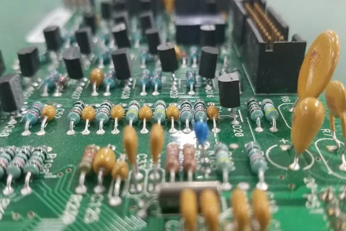
Modern 5G/6G RF unit (RU) PCBs are highly integrated. They pack BGA/QFN digital and RF ICs assembled via SMT assembly, while key parts—high-power connectors, high‑Q cavity filters, heavy inductors—still use THT/through-hole soldering for mechanical strength and specific electrical behavior. This mixed SMT+THT layout makes traditional full wave soldering impractical.
Full wave solder immerses the whole board in molten solder—destructive for already-assembled, heat-sensitive parts (BAW/SAW filters, precision clocks). Selective wave soldering solves this by using a programmable mini solder nozzle to locally solder only selected THT joints, leaving the rest of the PCB away from high heat.
Key benefits:
- Minimized thermal stress: heat is localized to target joints, protecting sensitive SMT parts—critical for mmWave performance on high-frequency PCB.
- High process flexibility: handles dense layouts; even THT parts surrounded by tall BGA can be soldered with nozzle customization and precise path planning.
- Consistent solder quality: computer control stabilizes time/temperature/solder volume per joint—critical across NPI EVT/DVT/PVT.
For manufacturers like HILPCB, mastering Selective wave soldering is a baseline capability to deliver complex 5G/6G boards.
High‑Q filters, parasitics, and rejection: why the solder process is a performance variable
In 5G/6G RF front ends, filters and duplexers (Duplexer/Multiplexer) define SNR and anti-interference capability. Whether LC, SAW/BAW, or cavity resonators, the goal is low insertion loss and high out-of-band rejection. In real assemblies, soldering often becomes a major variable.
Any solder joint introduces parasitic inductance/capacitance. At multi‑GHz to tens of GHz, even sub‑pF parasitics can shift center frequency or create ripples. Manual soldering or unstable THT/through-hole soldering yields inconsistent joint geometry and solder volume, causing unit‑to‑unit RF variation.
Selective wave soldering reduces this variability:
- Joint geometry control: stabilized solder flow and volume create smooth, repeatable joints, reducing parasitic inductance variation.
- Ground path reliability: for filter grounding, consistent low-impedance ground joints directly support high rejection.
- Bridge avoidance: for dense THT connectors, selective control reduces solder bridges, lowering unintended coupling and crosstalk.
In HILPCB’s flow, for RF boards using low-loss materials like Rogers PCB, engineers define Selective wave soldering parameters during DFM/DFT/DFA review to keep S-parameter results aligned to expectations.
Soldering process impact on RF filter performance
| Metric | Manual / full wave | Selective Wave Soldering |
|---|---|---|
| Center frequency shift | Larger and inconsistent; depends on solder volume/operator | Very small and repeatable; parameters precisely controlled |
| Insertion Loss | May increase due to poor joints or excess solder | Best joints minimize added loss |
| Rejection | Degrades with bad grounding or bridges | Stable grounding supports high rejection |
| Unit-to-unit consistency | Low; hard to scale | High; suitable from prototype to volume |
DFM/DFT/DFA review: optimizing Selective wave soldering from the design stage
A strong product is not “created” on the production line—it’s “locked in” at the design stage. DFM/DFT/DFA review turns manufacturing constraints into predictable outcomes, and it is especially important when Selective wave soldering is used.
Early in NPI EVT/DVT/PVT, design and manufacturing engineers should review:
- Component spacing (keep-out zones): the nozzle needs mechanical clearance; define keep-outs around THT parts considering nozzle size, approach angle, and component height.
- Soldering pallet design (Fixture Design): to protect SMT parts during selective solder, a custom pallet (Pallet) typically masks most areas and exposes only THT pins. Material (e.g., titanium), opening accuracy, and thermal conductivity affect results.
- Thermal mass balancing: pins tied to large ground copper vs. thin signal traces heat differently. Use thermal relief pads or process tuning (preheat/solder time) so all pins reach solder temperature.
- DFT / testability: Fixture design (ICT/FCT) needs test points that do not conflict with pallet clamps or selective-solder access.
Doing a thorough DFM/DFT/DFA review early avoids late-stage surprises, reduces rework cost, and shortens time-to-market. HILPCB’s prototype assembly includes DFM/DFA analysis to mitigate risk at the source.
Insertion loss / rejection / group delay: optimizing RF performance via solder quality
For 5G/6G, insertion loss, out-of-band rejection, and group delay are core RF metrics. Solder quality impacts all three:
Insertion loss: imperfect joints (cold solder, oxidation, insufficient wetting) add contact resistance and increase loss—amplified at mmWave. Selective wave soldering stabilizes joints to meet IPC-A-610 Class 3, forming reliable IMC and minimizing added loss.
Rejection: poor ground joints or solder bridges create coupling paths and degrade rejection—especially painful in O-RAN environments. Selective solder improves ground integrity and isolation.
Group delay: while mainly set by topology, variation in joint parasitics introduces random phase variation across units. Repeatable joints stabilize phase response, supporting eCPRI clock sync.
How solder quality impacts key RF metrics
Insertion loss
Low-quality joints: higher resistance, strong attenuation
High-quality joints: minimized path resistance, stable amplitude
Rejection
Poor grounding: coupling paths, lower rejection
Reliable ground: stronger shielding, higher rejection
Group delay consistency
Parasitic variation: phase mismatch, waveform distortion
Consistent joints: stable phase across production lots
Fixture design (ICT/FCT): co-design with Selective wave soldering
DFM and DFT must be co-optimized. When planning Selective wave soldering, you must consider later testing—especially ICT and FCT fixture design (Fixture design (ICT/FCT)).
Solder pallets and test fixtures are functionally separate, but they must be co-designed:
- Space conflicts: pallet clamps/pins must not collide with ICT pogo areas or press mechanisms.
- Test-point accessibility: ensure required test points remain accessible after soldering; large THT parts may block nearby points—route points to open areas if needed.
- Double-sided complexity: complex boards with THT on both sides may need two selective-solder operations and more complex dual-sided fixtures—requiring early 3D verification.
A strong Turnkey Assembly provider like HILPCB aligns soldering and test teams early, avoiding late design changes and expensive fixture surprises.
De-embedding and S-parameter consistency: validating post-solder RF performance
“What you measure is what you get” is every RF engineer’s dream—but board-level S-parameter measurement includes the entire path (fixture, probes, cables). To evaluate real device performance, you need de-embedding to remove fixture effects.
Common methods include TRL (Thru-Reflect-Line) and LRM (Line-Reflect-Match), which require calibration structures on the same PCB. To validate Selective wave soldering stability, measure de-embedded S-parameters across multiple samples and analyze consistency.
Typical validation flow:
- Baseline: early in NPI EVT/DVT/PVT, test a few “golden” hand-soldered samples to capture ideal S-parameters and analyze on Smith Chart.
- Build sample lot: produce 20–50 boards via Selective wave soldering.
- Statistical analysis: compare mean/std distribution to the baseline. A stable process yields tight normal distributions overlapping the baseline.
- Trace-back: if results drift or spread, trace solder parameters (temperature/time/solder flow), pallet design, or PCB incoming variation.
This data-driven closed loop is how 5G/6G products scale from lab to volume while maintaining RF performance.
S-parameter consistency validation flow
- 1. Calibration structures: integrate TRL/LRM de-embedding patterns on the PCB.
- 2. Golden baseline: precision solder and test reference boards to define baseline S-parameters.
- 3. Batch assembly: build statistical samples via standardized Selective wave soldering.
- 4. Automated measurement: use probe stations and VNA for automated S-parameter tests.
- 5. Data analysis: apply statistics to compare distributions to the baseline and assess stability.
- 6. Process optimization: continuously tune parameters to close the loop.
Conclusion: Selective wave soldering is the required path for high-performance 5G/6G manufacturing
As 5G/6G moves to higher frequency and higher density, PCB design and assembly complexity grows exponentially. In this context, Selective wave soldering is no longer an optional advanced process—it is a core technology to ensure mixed-technology RF boards achieve performance, reliability, and repeatability. It balances the precision of SMT assembly and the robustness of THT/through-hole soldering, using localized heat and solder control to minimize negative impact on sensitive RF devices.
From DFM/DFT/DFA review to solder process control, and then Fixture design (ICT/FCT) plus S-parameter validation, Selective wave soldering runs through the full NPI EVT/DVT/PVT workflow. It’s not only about soldering—it’s a system engineering method to translate design intent into hardware without losing performance. For HILPCB, continuous optimization of this capability is fundamental to delivering high-performance, high-reliability 5G/6G products at scale.
Common Questions
Why is selective wave soldering important for 5G and 6G mmWave boards?
These boards often combine dense SMT RF circuitry with through-hole connectors, shields, or power parts that still need robust joints. Selective wave soldering gives localized heat control so sensitive high-frequency structures are protected during assembly.
Can solder consistency really affect RF performance?
Yes. Variations in solder shape, parasitics, and connector termination geometry can change impedance, insertion loss, and phase behavior. On multi-gigahertz links, those assembly differences can be measurable and sometimes significant.
Why do fixture design and RF validation need to be considered together?
Because solder pallets, access windows, and test fixtures all influence what can be assembled and measured on the final board. Planning them together helps avoid late-stage conflicts between manufacturability and RF test coverage.
What should teams verify before scaling a selective-soldered 5G/6G product?
They should check joint repeatability, S-parameter consistency, process-window stability, and compatibility with downstream ICT or FCT. The goal is to prove that RF performance survives real production, not just lab samples.