
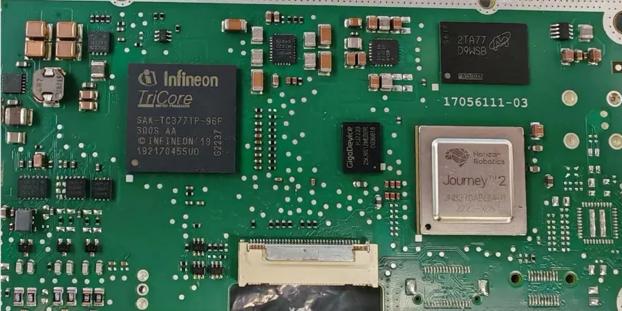
As ADAS and EV power systems push toward higher integration, higher power density, and stricter functional-safety requirements, PCB reliability and assembly quality have become the foundation of vehicle safety and performance. While SMT dominates high-density electronics, THT/through-hole soldering remains indispensable in automotive applications—especially for power devices, connectors, and high-stress components—thanks to its mechanical strength, heat dissipation capability, and high-voltage robustness. From an automotive electronics engineer’s perspective, this article explains how THT/through-hole soldering supports ISO 26262/ASIL-D goals and helps ADAS and EV power PCBs achieve long-term reliability under extreme conditions.
Functional safety breakdown: ASIL targets, hardware metrics, and diagnostic coverage
Under ISO 26262, any safety-related electronic system must undergo rigorous HARA to determine its ASIL level. From ASIL-A up to ASIL-D, higher levels demand stricter reliability and fault-tolerance. For ADAS decision units or EV BMS, ASIL-C or ASIL-D is commonly required.
Meeting these goals is fundamentally a hardware challenge—and THT/through-hole soldering plays a critical role. High ASIL levels require extremely low hardware failure rates, which ties directly to two core hardware metrics: Single-Point Fault Metric (SPFM) and Latent Fault Metric (LFM). For ASIL-D, ISO 26262 typically requires SPFM > 99% and LFM > 90%, meaning the system must detect and control the vast majority of single-point and latent faults.
The mechanical robustness of THT joints provides a physical baseline for these targets. For example, on power connectors, large inductors, or power transistors exposed to vibration and thermal shock, THT delivers far stronger anchoring than SMT—reducing the probability of stress-driven interconnect failures. In addition, with precise Fixture design (ICT/FCT), critical THT joints can be covered by 100% in-circuit test (ICT) and functional test (FCT), verifying electrical integrity and improving Diagnostic Coverage (DC) to support LFM. A well-designed fixture is a key enabler for DC verification.
Redundancy and fail-safe: architecture, monitoring, and fault handling
To meet ASIL-D, redundancy (lockstep cores, channel redundancy) and fail-safe mechanisms are standard. These architectures depend on stable, predictable hardware. In EV high-voltage inverters or onboard chargers (OBC), high-current paths often use heavy copper PCB and THT-mounted power modules, busbars, or large capacitors.
In this scenario, THT/through-hole soldering delivers clear advantages:
- Current-carrying capability: Thick leads and large pads can safely carry hundreds of amps with lower heat rise and voltage drop.
- Mechanical stability: Under shock and vibration, THT joints resist mechanical fatigue, preventing physical disconnects that would undermine redundancy.
- Predictable failure modes: Typical THT solder failure modes (cold solder, weak joints) are easier to detect via monitoring (voltage/current sensing) or diagnostics (X-Ray), supporting reliable fault-handling strategies (channel switching, safe state).
During production, a robust Traceability/MES system tracks each THT joint’s process parameters (temperature, time) and operator information—providing hard evidence for failure analysis and root-cause traceability, which is essential to ISO 26262 process compliance.
Implementation path: applying THT in ASIL-D systems
- Safety goal definition: Identify hazards related to THT connectors/power components (opens, shorts) and define safety goals (e.g., prevent unintended acceleration).
- FMEA/FMEDA analysis: Perform failure-mode/effects and diagnostic analysis for THT joints, estimate failure rates, and include them in SPFM/LFM calculations.
- Design & process specifications: Define strict PCB pad rules (IPC), soldering processes (e.g., Selective wave soldering), and inspection criteria (IPC-A-610 Class 3).
- Test & validation: Design dedicated Fixture design (ICT/FCT), combined with ESS and durability tests, to validate THT joint reliability across the full lifecycle.
- Production control & traceability: Deploy Traceability/MES to trace everything from component lots to solder parameters, ensuring production consistency.
THT/through-hole soldering in high-voltage/high-current designs: thermal management and mechanical strength
EV power stages (inverters, DC/DC converters) operate under high voltage (400V/800V) and high current, making thermal management a core design challenge. For THT components—especially power devices—leads are not only electrical conductors but also key heat paths.
- Enhanced heat dissipation: THT leads pass through the PCB, enabling soldering and heat spreading on both sides. With large copper areas and thermal vias, heat can be efficiently conducted into the heat-spreading layers of high-thermal PCB or into external heatsinks. This 3D thermal structure is difficult to match with SMT parts.
- Handling thermal cycling: Automotive electronics must survive -40°C to 125°C (or higher). CTE mismatch among leads, solder, and PCB laminate creates significant stress on joints. With larger solder volume and barrel-shaped structures, THT joints absorb and distribute stress more effectively—improving fatigue life under thermal cycling.
To further improve reliability in harsh environments, Potting/encapsulation is often used to protect the entire PCBA. Potting fully covers THT parts and joints, providing moisture/dust/chemical protection and vibration resistance, while also assisting heat transfer—an ultimate safeguard for long-term high-voltage safety.
Automotive-grade components, derating, and environmental robustness
All automotive electronics must comply with AEC-Q standards (e.g., AEC-Q100 for ICs, AEC-Q200 for passives). The same principle applies when selecting THT components. But compliance alone is not enough—robust derating is required.
Derating means operating components below their maximum ratings to build safety margin and extend lifetime. For THT power resistors, electrolytics, and inductors, consider:
- Temperature derating: Keep core temperature well below spec limits at worst-case conditions.
- Voltage derating: In high-voltage systems, include transient overvoltage; rated voltage for THT capacitors/connectors must have sufficient margin.
- Current derating: Keep lead current below rating to control temperature rise and electromigration risk.
For environmental adaptation, beyond potting, Conformal coating is widely used. It forms a thin but robust protective film on the PCBA surface—isolating moisture, salt fog, and contaminants—and preventing electrochemical migration and corrosion on THT joints. This is critical for ECUs deployed in harsh locations (chassis, engine bay). Choosing the right Conformal coating material and process is key to passing salt-fog and damp-heat tests.
Key reminders: core considerations for automotive-grade THT
- Functional safety first: Put ISO 26262 requirements first; ensure THT selection and placement serve ASIL targets and hardware metrics.
- Mechanical & thermal stress: Evaluate vibration, shock, and thermal cycling impacts on THT joints; use simulation early.
- Process controllability: Prefer automated, high-precision soldering such as Selective wave soldering to ensure consistency.
- All-around protection: Select Conformal coating or Potting/encapsulation based on the environment; build layered defenses.
- Design for test (DFT): Plan testability in the design phase; optimize test-point layout and pair it with efficient Fixture design (ICT/FCT) for 100% coverage.
Production consistency: PPAP/APQP and a traceable manufacturing system
One of the core requirements for automotive products is production consistency. OEMs demand strict quality management, where APQP and PPAP are two key pillars.
In turnkey PCBA assembly involving THT/through-hole soldering, this means:
- APQP phase: Early in design, plan the THT soldering process flow, define key process parameters (SPC), design dedicated tooling/fixtures, and run Process FMEA to identify risks and preventive actions.
- PPAP phase: Before mass production, submit a complete PPAP package including process flow, PFMEA, Control Plan (CP), and process capability studies (Cpk/Ppk), proving stable and consistent production capability for THT assemblies.
All of this relies on a strong Traceability/MES. It records every step—from incoming materials, PCB bare-board data, component lots, equipment parameters, AOI/X-Ray results, to final test data. When issues occur, Traceability/MES enables rapid trace-back to batch, equipment, and time window, triggering an 8D problem-solving workflow for fast response and continuous improvement.
Advanced soldering and protection: from Selective wave soldering to Conformal coating and Potting/encapsulation
Traditional wave soldering works for pure THT boards, but on mixed-technology boards (SMT + THT) it can damage SMT components. This is why Selective wave soldering has become the mainstream automotive THT process.
Selective wave soldering uses a small, precisely controlled solder fountain/nozzle to solder only specified THT joints without affecting nearby SMT parts. Key benefits include:
- High precision and flexibility: Parameters can be tailored for different THT component types.
- Lower thermal shock: Localized heating avoids heating the entire PCB.
- High-quality joints: With tight control, it delivers robust joints meeting IPC-A-610 Class 3 expectations.
After soldering, protection is the last line of defense for long-term reliability. Conformal coating provides baseline environmental protection. For modules exposed to extreme vibration, humidity, or chemical risk (e.g., chassis-mounted controllers), Potting/encapsulation is often required. While it adds cost and weight, its physical protection and structural reinforcement are unmatched—keeping THT components stable under high stress.
Conclusion
THT/through-hole soldering is far from obsolete. In automotive ADAS and EV power electronics—where high voltage, high current, vibration, and harsh thermal cycling are the norm—it remains a key process to achieve the highest reliability. By integrating THT into ISO 26262 functional-safety workflows, combining advanced Selective wave soldering, comprehensive Traceability/MES, and layered protection such as Conformal coating and Potting/encapsulation, we ensure each THT joint meets automotive-grade standards. As a professional through-hole assembly service provider, HILPCB supports customers with strong engineering and strict quality control to build safe, reliable, high-performance automotive electronics.
Common Questions
Why does THT remain important in automotive ADAS and EV power electronics?
Through-hole connections still provide strong mechanical anchoring and dependable high-current performance in harsh automotive environments. That makes THT especially valuable for heavy components, power devices, connectors, and safety-critical assemblies.
Why is selective wave soldering important on mixed-technology automotive boards?
Automotive boards often combine SMT and THT on the same assembly, and full-board wave soldering can damage sensitive SMT areas. Selective wave soldering gives tighter thermal control and more precise joint formation where THT reliability is required.
Why do traceability, MES, and automotive process discipline matter so much?
Automotive production requires consistent, auditable process control from material lot to final test record. Traceability and MES systems make it possible to isolate issues quickly, support PPAP expectations, and sustain long-term quality improvement.
Why do conformal coating and potting affect long-term reliability?
After soldering, environmental protection becomes critical for modules exposed to vibration, humidity, chemicals, and thermal stress. Conformal coating and potting help preserve joint integrity and structural stability over the full service life.