
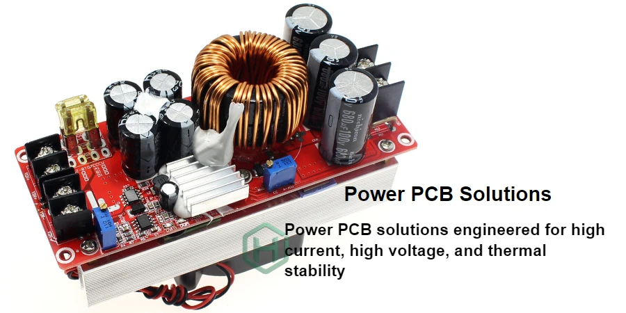
A train power PCB is the board-level power-input, conversion, distribution, monitoring, and protection platform inside rolling-stock electronic equipment. Its design must translate the vehicle supply, installation environment, functional behavior, service life, and railway standards into verifiable electrical, thermal, mechanical, EMC, and manufacturing controls.
Key Takeaways
- Define whether the board powers control electronics, communications, doors, braking support, passenger systems, or a safety-related function; “train power PCB” does not describe one voltage or architecture.
- EN 50155:2026 covers broad rolling-stock electronics, but it is not a PCB-factory certificate and does not define practices for achieving a Safety Integrity Level (SIL).
- Complete onboard power converters and semiconductor drive units may fall under EN 61287-1 rather than the main EN 50155 scope. Station equipment such as platform screen doors also needs its own standards analysis.
- Derive protection, ride-through, inrush, isolation, supervision, and safe-state behavior from the specified vehicle supply and performance criteria.
- Creepage and clearance depend on working voltage, overvoltage, pollution, material, altitude, coating, and insulation function. No universal “railway spacing” value exists.
- High-Tg laminate, heavy copper, conformal coating, potting, and environmental stress screening are conditional design/process choices, not mandatory features of every rail PCBA.
- IEC 61373 shock and vibration tests depend on equipment location and mounting category. The PCB, enclosure, connectors, fasteners, and cable loads must be validated together.
- Separate type qualification, production controls, routine tests, system validation, and change-triggered requalification.
Contents
- What Is a Train Power PCB?
- Which Railway Standards Apply?
- How Do Installation Conditions Become PCB Requirements?
- How Should the Railway Power Input Be Designed?
- How Are Isolation, Creepage, and Clearance Determined?
- When Do Heavy Copper, High Tg, Coating, or Potting Help?
- How Should EMC Be Designed and Verified?
- How Do Shock and Vibration Change the PCBA?
- How Does a Power PCB Support Functional Safety?
- What Qualification and Production Evidence Is Needed?
- How Should Long Railway Lifecycles Be Controlled?
- What Should a Train Power PCB RFQ Include?
What Is a Train Power PCB?
The term covers different hardware classes. A low-power isolated control supply is not an auxiliary converter, gate-driver board, battery charger, or complete traction converter; their voltage, energy, fault, cooling, and compliance boundaries differ.
Typical board functions include:
- accepting a specified DC or AC vehicle supply and limiting inrush, conducted disturbance, reverse-energy paths, and abnormal input conditions
- converting and distributing isolated or non-isolated rails to processors, sensors, communications, actuators, relays, displays, or safety-related channels
- supervising input/output voltage, current, temperature, sequencing, insulation or ground faults where required, and reporting diagnostic status
- maintaining defined behavior through supply variation, dips, interruptions, brownout, startup, shutdown, and recovery
- containing failures so one shorted device, open sense path, overheated connector, or corrupted control signal does not create an unacceptable system state
Do not assume the PCB directly converts catenary or third-rail voltage. Many units receive a vehicle battery or auxiliary supply, while complete high-power converters have another standards scope. Platform screen doors are normally wayside equipment, so rolling-stock requirements do not automatically apply.
Which Railway Standards Apply?
EN 50155:2026 supersedes EN 50155:2021 and covers rolling-stock electronic equipment for control, regulation, protection, diagnostics, and energy supply. It includes safety-related hardware but not practices for achieving a SIL or functional safety. EN 50716 addresses onboard software development.
A fabricator does not become “EN 50155 certified” by producing a railway PCB. The equipment manufacturer defines applicable clauses, classes, criteria, tests, evidence, and deviations; the supplier builds to that controlled specification.
Standards form a responsibility stack
| Requirement area | Common reference | What it changes at board level |
|---|---|---|
| Rolling-stock electronic equipment | EN 50155:2026; IEC 60571 where contractually applicable | Supply behavior, environment, design/construction, documentation, reliability, maintainability, and equipment tests |
| Complete onboard power converter | EN 61287-1 | Converter-specific electrical, protection, thermal, control, and test requirements outside or beyond EN 50155 |
| EMC for rolling-stock apparatus | EN 50121-3-2 | Conducted/radiated emissions and immunity interfaces, grounding, filtering, shielding, and test configuration |
| Insulation coordination | EN 50124-1 and applicable converter/equipment standard | Working voltages, overvoltage, pollution, creepage, clearance, insulation and dielectric test strategy |
| Shock and vibration | IEC 61373 | Installation category, axes, test levels/durations, mounting fixture, structural and functional acceptance |
| Fire behavior | EN 45545-2 within the vehicle fire-safety plan | Material/assembly selection, hazard level and requirement set as allocated by the vehicle/equipment design |
| Railway software | EN 50716 | Hardware support for boot, supervision, update, diagnostics, safe outputs, configuration, and traceability |
| RAMS and functional safety | EN 50126 series; EN 50129 for relevant signalling applications such as axle counters | Safety requirements, independence, failure-rate evidence, diagnostics, configuration control, and safety case |
| Railway quality management | ISO 22163 where required by the supply chain | Organization-level QMS processes and scope; it does not certify the PCB product or SIL |
The contract must identify editions and precedence. Do not substitute a new edition into an approved project without design-authority and requalification review.
How Do Installation Conditions Become PCB Requirements?
Temperature, vibration, humidity, and supply variation are headings, not a specification. The equipment owner must allocate actual conditions to the board and enclosure.
Installation-to-qualification matrix
| System input | Questions to freeze | PCB/PCBA consequences | Evidence to plan |
|---|---|---|---|
| Vehicle power interface | Nominal supply, continuous range, dips/interruptions, surges, source impedance, reverse polarity, grounding, available fault energy | Protection topology, hold-up, inrush, fuse coordination, isolation, connector/copper rating, discharge | Input-profile tests, abnormal/fault tests, protection coordination, recovery behavior |
| Installation location | Inside conditioned cabinet, equipment compartment, roof, underframe, bogie/axle-adjacent, or wayside | Temperature, condensation, pollution, vibration category, ingress, corrosion, coating, retention | Thermal/humidity tests, IEC 61373 category and fixture, enclosure/IP validation |
| Load and performance | Rail currents, transient demand, startup order, allowable droop, permitted degradation, safe state | Converter topology, decoupling, sequencing, supervisors, output disconnect, diagnostics | Load-step, brownout, startup/shutdown, short/open, safe-state and recovery tests |
| EMC interfaces | Cable length/type, shield termination, chassis, return paths, external ports, nearby traction switching | Filter stages, common-mode paths, TVS placement, grounding, connector pinout, layout partitioning | EN 50121-3-2 test plan, cable/ground configuration, pre-compliance correlation |
| Safety allocation | Hazard, safety function, SIL if allocated, independence, diagnostic coverage, common-cause assumptions | Redundant channels, separation, monitoring, de-energized state, component derating and traceability | FMEA/FMEDA inputs, fault injection, independence review, safety-case evidence |
| Service and lifecycle | Operational life, repair level, spares, firmware/configuration, obsolescence, permitted changes | Component selection, test access, serialization, replaceable modules, records and alternates | Qualification baseline, production record, PCN/change process, regression/requalification matrix |
Every board feature should trace to an allocated condition and evidence plan; otherwise “railway grade” is unverifiable.
How Should the Railway Power Input Be Designed?
The input stage must survive its supply profile without disturbing the vehicle bus. A converter copied from another voltage or interruption class can produce poor hold-up, excess inrush, or unsafe restart.
Create an input power contract that defines:
- continuous voltage range, allowable ripple, source impedance, grounding and return arrangement
- overvoltage, surge, transient, dip, interruption, reverse-polarity, and reconnection profiles from the applicable equipment specification
- input current, startup current, precharge/inrush behavior, fuse/breaker coordination, and maximum available fault energy
- required output performance during each input event: normal operation, limited degradation, data retention, controlled shutdown, or restart
- isolation requirement and test voltage, including primary-to-secondary, primary-to-chassis, output-to-chassis, and communication paths
- discharge time, stored energy, service hazards, and behavior after a protection device operates
Layer protection: fusing limits sustained fault energy; suppressors clamp within their energy rating; filters control noise; inrush control protects distribution; reverse/backfeed protection manages incorrect paths; converter control handles undervoltage and restart. Coordinate every device with source and load.
Hold-up follows load power, usable bus voltage, efficiency, droop, and interruption time, but raises inrush, stored energy, size, and vibration load. Controlled state retention may be better than full ride-through.
Output protection should distinguish overload, short circuit, regulation failure, sense-path failure, and external backfeed. Safety-related loads may need independent overvoltage protection or physical disconnection rather than firmware-only supervision. Verify restart policy: automatic hiccup, latched shutdown, delayed retry, or maintenance reset can have different system consequences.
How Are Isolation, Creepage, and Clearance Determined?
Railway spacing is an insulation-coordination result, not a fixed number. EN 50124-1 and the applicable equipment/converter standard connect working voltage, transient overvoltage, pollution degree, material group, altitude, insulation type, and construction to clearance, creepage, and dielectric tests.
Prepare an insulation diagram before layout. Mark every boundary between input, outputs, chassis, accessible metal, communications, sensors, heatsinks, mounting hardware, shields, test points, and secondary circuits. For each boundary record:
- normal and abnormal working voltage plus expected transient stress
- functional, basic, supplementary, reinforced, or other allocated insulation function
- required creepage, clearance, slots/barriers, component ratings, and test method
- pollution/condensation assumptions, coating or potting credit if permitted, and manufacturing tolerance
- connector pin sequencing, unmated exposure, fuse/protection location, and fault-energy path
Solder mask is not automatically reliable insulation. Conformal coating can support pollution control only when the selected standard, coating type, process, thickness, coverage, adhesion, aging, inspection, repair, and environmental validation justify that credit. Slots can increase surface distance but also weaken the board and change contamination or coating behavior.
Metal heatsinks, screws, standoffs, card guides, shields, and enclosure ribs frequently defeat an otherwise correct two-dimensional PCB spacing review. Check the assembled three-dimensional geometry and tolerances.
When Do Heavy Copper, High Tg, Coating, or Potting Help?
Materials and protective processes solve specific stresses. Treating them as universal railway requirements adds cost and sometimes creates new failure modes.
| Option | Valid design driver | Risks and tradeoffs | Required confirmation |
|---|---|---|---|
| Heavy copper | Current density, DC drop, heat spreading, fuse behavior, mechanical conductor robustness | Etch compensation, fine-feature limits, resin fill, copper balance, assembly thermal mass | Finished copper, geometry, temperature-rise/DC-drop analysis, fabrication cross-section |
| High-Tg laminate | Assembly excursions, operating temperature, dimensional stability, chosen reliability margin | Tg alone does not define decomposition temperature, Z-axis expansion, CAF, moisture, or vibration reliability | Full material datasheet, stackup, thermal cycles, processing and qualification evidence |
| Conformal coating | Condensation, contamination, corrosion, insulation or maintenance strategy | Shadowing, bubbles, poor adhesion, connector contamination, trapped residues, repair difficulty | Chemistry, thickness/coverage, masking, cleanliness, cure, inspection, rework and aging plan |
| Potting/encapsulation | Mechanical support, environmental sealing, dielectric or thermal path | Added mass, CTE stress, exotherm, hotspots, poor repairability, component incompatibility | Material compatibility, cure profile, void control, thermal/mechanical validation, service plan |
| Metal substrate or local heat spreader | Defined thermal path for power devices | Isolation construction, CTE mismatch, weight, routing limits, assembly and enclosure interface | Thermal model, dielectric rating, flatness, attachment and environmental tests |
Size copper from current, allowable temperature rise, length, ambient, adjacent heating, via transitions, connector/contact resistance, and protection clearing time. Three-ounce copper is not automatically better than a wider one-ounce plane, busbar, press-fit power connector, or separate power module. For project-specific feasibility, compare the submitted construction through heavy copper PCB and high-Tg PCB reviews; actual material, copper, spacing, qualification, and availability must be confirmed in the quote.
Thermal analysis should use the enclosure, airflow/conduction path, altitude, duty cycle, component losses, tolerances, aging, and nearby heat sources. Thermal vias only move heat to another layer or surface; they do not create a path from the assembly to the ambient environment.
How Should EMC Be Designed and Verified?
Railway power electronics sit between a noisy vehicle supply and sensitive loads. EN 50121-3-2 addresses EMC for rolling-stock apparatus, but the equipment test configuration—cables, lengths, shields, grounding, ports, operating modes, loads, enclosure, and auxiliary equipment—determines whether results represent deployment.
Partition the PCB into dirty input, switching power, isolation, clean output, sensing/control, and external-interface zones. Keep high-di/dt loops compact; place suppressors and common-/differential-mode filtering at the connector they protect; control return currents; bond shields according to the equipment grounding strategy; and keep surge current away from measurement references and communication grounds.
An input filter can destabilize a regulated converter when impedances interact. Review filter damping and converter input impedance across load, temperature, and source conditions. Protective devices also add capacitance and leakage that can affect isolation monitoring or high-speed communications.
Pre-compliance should reproduce the final cable and chassis arrangement. Monitor output regulation, resets, data corruption, diagnostic alarms, safe-state behavior, and recovery during immunity tests—not only whether the unit remains powered. A board that silently changes an actuator command is not validated by an illuminated power LED.
How Do Shock and Vibration Change the PCBA?
IEC 61373 does not impose one universal “Class 1 A/B” test on every railway board. Test category and class depend on where and how equipment is mounted, such as vehicle body, bogie, or axle-related locations. The equipment owner must specify the applicable configuration and acceptance criteria.
Use modal and mechanical review to identify board resonances, deflection, connector motion, cable loads, and heavy-component stress. Inductors, transformers, electrolytic capacitors, heatsinks, relays, busbars, and tall connectors deserve explicit retention and solder-joint analysis. Adhesive, clamps, brackets, staking, potting, and fasteners need controlled materials and processes; adding adhesive without compatibility and rework analysis is not automatically an improvement.
The qualification article should match production mounting, enclosure, board thickness, stiffeners, fastener torque, cable dress, connector locking, heatsink, and component retention. Functional monitoring during and after test should cover rail outputs, resets, communications, diagnostics, intermittent connections, and insulation as allocated. Inspect for cracked solder, fretting, connector movement, fastener loosening, component body damage, and laminate/via damage.
How Does a Power PCB Support Functional Safety?
A PCB does not receive a generic SIL based on its application name. SIL is allocated to a safety function through the railway safety lifecycle and system architecture. EN 50155:2026 covers hardware used in safety-related systems but excludes the practices necessary to achieve functional safety. Relevant EN 50126/EN 50129 processes, application requirements, and safety case determine the evidence.
Power fault-containment matrix
| Failure | Potential system effect | Board-level control | Verification evidence |
|---|---|---|---|
| Input protection short/open | Loss of supply, upstream bus disturbance, fire/thermal event | Coordinated fuse/protection, fault-current path, thermal separation | Abnormal/fault test, protection coordination, temperature inspection |
| Converter switch short | Output overvoltage, loss of isolation, overheated magnetics | Independent OVP/disconnect where required, isolation design, energy limiting | Injected/simulated fault, OVP threshold and response, dielectric evidence |
| Feedback open/short/drift | Output rises, collapses, or oscillates | Plausibility checks, independent supervisor, safe restart policy | Sense fault injection across voltage, temperature, startup and load |
| One output rail lost | Unsafe partial operation or misleading diagnostics | Power-good interlocks, sequencing, de-energized outputs, system notification | Rail-loss matrix and safe-state/system integration test |
| Connector/contact degradation | Local heating, intermittent reset, arcing | Current margin, parallel contacts where justified, temperature monitoring, retention | Worst-case contact/DC/thermal analysis and vibration/load test |
| Common-cause disturbance | Redundant channels fail together | Physical/electrical separation, independent protection/supply where allocated | Independence/common-cause review, EMC/fault injection |
| Overtemperature | Accelerated aging, shutdown, uncontrolled output | Sensor placement, derating, independent cutoff where required | Worst-case thermal and sensor-fault tests |
| Corrosion/contamination | Leakage, tracking, intermittent sensing | Cleanliness, material/coating strategy, spacing and enclosure controls | Process records, humidity/condensation/corrosion tests as specified |
The safety team owns hazard analysis, SIL allocation, failure data, diagnostics, independence, common-cause analysis, and risk acceptance. The supplier supports the case with traceability, inspection, tests, and change records. Duplicated channels are not independent if they share regulators, connectors, references, protection, software, or vulnerabilities.
What Qualification and Production Evidence Is Needed?
Type qualification, design verification, production process validation, routine test, and environmental stress screening are different activities. Do not promise that every PCBA receives vibration, temperature cycling, EMC, X-ray, or full functional testing unless the approved plan requires it.
| Evidence layer | Typical content | Primary owner |
|---|---|---|
| Design analysis | Power profile, protection coordination, insulation, thermal, EMC, mechanical, derating, FMEA/FMEDA inputs | Equipment design authority with specialist support |
| PCB fabrication | Netlist/electrical test, material/stackup records, dimensional/visual acceptance, copper/plating and microsection evidence, cleanliness or impedance where specified | Fabricator to drawing and purchase order |
| PCBA process | Solder profile, AOI/X-ray where risk-appropriate, workmanship acceptance, coating/potting validation, programming and serialization | Assembler to approved process/test specification |
| Engineering verification | Input events, load/fault behavior, dielectric, thermal, EMC pre-compliance, shock/vibration article, diagnostics and recovery | Equipment development team and qualified labs |
| Type/routine testing | Tests and sample/routine coverage required by the equipment standard and customer qualification plan | Equipment manufacturer with test partners |
| System validation | Vehicle supply, harness, enclosure, cooling, loads, communications, safety functions, installation and service behavior | Vehicle/subsystem integrator and legal manufacturer |
Environmental stress screening may detect latent defects when justified by reliability analysis; it is not qualification or automatically required on every unit. Define profile, monitoring, acceptance, failure analysis, and feedback so screening does not consume useful life.
HILPCB can review manufacturability, assembly, coating/potting instructions, traceability, and customer-defined inspection/test packages through turnkey PCB assembly. The quotation must confirm the actual process capability, certificates and scope, test equipment, sampling, data package, and responsibilities.
How Should Long Railway Lifecycles Be Controlled?
Rail projects need long support, but no supplier should promise 15–30 years of unchanged production without a lifecycle contract. Components, materials, fixtures, and tools can become obsolete or change.
Create a lifecycle baseline containing approved manufacturer part numbers, alternates, material constructions, firmware/configuration, process specifications, fixtures, golden units, test limits, calibration, and qualification evidence. Define:
- component lifecycle monitoring, counterfeit controls, PCN/end-of-life notification, last-time-buy authority, and storage limits
- alternate approval with electrical, thermal, mechanical, EMC, safety, software, and regulatory impact review
- preservation of manufacturing data, source/programming files, fixtures, test software, repair information, and configuration identifiers
- nonconformance, rework/repair, concession, field-return analysis, corrective action, and record-retention responsibilities
- regression and requalification triggers for component, laminate, copper, coating, layout, enclosure, firmware, supplier, or process changes
An alternate MOSFET can change gate charge, loss, EMC, fault behavior, and protection timing; a “drop-in” module can alter isolation, hold-up, inrush, and recovery. Lifecycle control is engineering, not only purchasing.
What Should a Train Power PCB RFQ Include?
Equipment and standards context
- rolling-stock or wayside application, equipment function, installation location, enclosure, cooling, operational life, maintenance level, and safety-function allocation
- applicable standards and editions, temperature/environment classes, IEC 61373 category/class, EMC ports/configuration, insulation requirements, fire-safety allocation, performance criteria, and customer specifications
- nominal supply plus continuous range, ripple, source impedance, dips, interruptions, surges, transients, reverse polarity, available fault current, grounding, and required behavior for each event
Fabrication and assembly package
- Gerber/ODB++ or IPC-2581, drill, netlist, drawings, controlled stackup, laminate/foil, finished copper, thickness, spacing/slots, surface finish, solder mask, marking, panel, and IPC class/revision
- BOM with approved manufacturers/alternates, centroid, assembly drawings, soldering limits, moisture handling, component retention, fasteners/torque, thermal interfaces, cleaning, coating/potting, masking, cure, inspection, and rework instructions
- safety-critical characteristics and components, insulation diagram, current/thermal-critical regions, connector and cable loads, enclosure/mounting data, firmware/programming, serialization, and configuration requirements
Test, quality, and lifecycle evidence
- fabrication/assembly inspection and sampling, type versus routine tests, functional/fault limits, fixtures, golden units, raw-data/report format, calibration, and acceptance ownership
- material/process traceability, certificates and QMS scope, nonconformance/rework authority, record retention, PCN/change notification, alternate approval, obsolescence, and requalification triggers
- prototype, qualification, pilot, and production quantities; packaging/storage; service spares; delivery schedule; and explicit customer-owned system tests
The supplier response should state exactly which materials, constructions, tolerances, coating/potting processes, inspections, tests, certificates, evidence, quantities, and lead times are confirmed for the build. Generic “railway grade” claims are not an acceptable substitute.
Standards and Responsibility Scope
Common references may include EN 50155:2026 for rolling-stock electronic equipment; EN 61287-1 for onboard power converters; EN 50121-3-2 for rolling-stock apparatus EMC; EN 50124-1 for insulation coordination; IEC 61373 for shock and vibration; EN 45545-2 for fire behavior; EN 50716 for railway software; the EN 50126 series and EN 50129 for applicable RAMS/safety-related signalling processes; ISO 22163 for railway-sector quality management where required; and IPC-2221, IPC-6012, IPC-A-600, J-STD-001, and IPC-A-610 for agreed PCB/PCBA design, performance, and acceptance. Confirm current national adoptions, editions, amendments, customer specifications, and precedence with the project authority.
The rolling-stock/subsystem manufacturer owns standards selection, equipment classification, vehicle supply and environment, functional-safety allocation, RAMS, EMC/insulation/fire strategy, qualification, system validation, and authorization. HILPCB is responsible only for fabrication, assembly, inspection, documentation, programming, and testing accepted in writing. PCB/PCBA delivery does not certify EN 50155 conformity, SIL, vehicle compatibility, fire safety, EMC, or complete-system reliability.
Common Questions
What is a train power PCB?
It is the PCB or PCBA that protects, converts, distributes, monitors, or controls electrical power inside railway electronic equipment. Its requirements depend on the actual supply, load, installation, safety function, and standards scope.
Is EN 50155 a PCB manufacturing certification?
No. EN 50155 defines requirements for rolling-stock electronic equipment. The equipment manufacturer allocates applicable requirements to the PCB/PCBA supplier and validates the complete unit. Supplier QMS certificates have separate scopes.
What changed with EN 50155:2026?
EN 50155:2026 supersedes the 2021 edition and updates scope, references, definitions, supply/environment requirements, reliability/maintainability, documentation, and tests. Existing projects should use the contractually approved edition until change impact is reviewed.
Does every train power PCB need heavy copper and high-Tg laminate?
No. Copper and laminate follow current, voltage drop, temperature, assembly, thermal cycling, mechanical, insulation, and reliability analysis. Heavy copper and high Tg are options, not proof of railway suitability.
Is conformal coating mandatory on every railway PCBA?
No. Use coating when the allocated condensation, pollution, corrosion, insulation, or maintenance strategy requires it. The chemistry, cleanliness, coverage, cure, inspection, aging, and repair process must be controlled.
What creepage and clearance should a railway power board use?
There is no universal value. Determine spacing from working voltage, transient stress, overvoltage, pollution, material group, altitude, insulation function, coating assumptions, applicable standards, and manufacturing tolerance.
Does a railway power PCB have a SIL rating?
Not by application name. SIL is allocated to a safety function and supported by system architecture, analysis, verification, configuration control, and a safety case. The PCB contributes evidence but does not establish SIL alone.
What should be tested before railway deployment?
Verify input events, protection and fault behavior, output/sequence, insulation, thermal, EMC, shock/vibration, diagnostics, recovery, production controls, and the assembled equipment in its representative vehicle interfaces and enclosure.
Convert the vehicle and equipment requirements into a controlled evidence package, then request a HILPCB engineering review and quote for the defined PCB/PCBA scope.