
In the early era of personal computing, connecting external devices was limited by hardware interfaces such as serial and parallel ports. Printers and scanners relied on bulky, low-speed connections, and users often had to install dedicated expansion cards. The introduction of the Universal Serial Bus (USB) standard in the mid-1990s provided a shared interface for peripheral data transfer and bus power.
What Are USB Ports?
USB (Universal Serial Bus) is a standardized technology that enables communication and power exchange between electronic devices. A USB port allows both digital data transmission and electric power delivery over a single cable, enabling functions such as file transfer, peripheral connection, and device charging.
Over time, the USB specification has evolved significantly, improving transfer speed, power capability, and connector design. Modern USB interfaces now serve not only computers but also smartphones, gaming systems, and industrial equipment.
The USB ecosystem today centers on four core aspects:
- Connector type (form factor)
- Data transfer speed and protocol
- Video and alternate-mode functionality
- Power delivery capability (USB PD standard)

Types of USB Ports
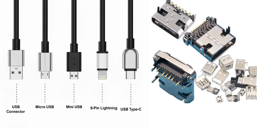
Several USB connector types exist, each optimized for specific devices. The main families include USB-A, USB-B, Mini-USB, Micro-USB, and USB-C.
USB-A: The original rectangular connector, still found on many desktop PCs, TVs, and game consoles. USB-A supports power and data transfer but is non-reversible, meaning it must be inserted in a specific orientation.
USB-B: A square-shaped connector typically used for printers and older external hard drives. Many modern devices have shifted to USB-C for compactness, but USB-B remains in legacy equipment.
Mini-USB: An older smaller connector used in cameras, MP3 players, and early gaming controllers. It has largely been replaced by Micro-USB and USB-C but remains in certain specialized devices.
Micro-USB: A small, non-reversible connector family used in phones, accessories and embedded equipment. The familiar USB 2.0 Micro-B and the wider SuperSpeed Micro-B have different contacts and data capabilities; do not infer the protocol from the word “Micro” alone.
USB-C: Introduced in 2014, USB-C is a compact, reversible connector. A port may provide USB 2.0 data, faster USB, video and/or negotiated power, depending on the implementation. Examples of higher-speed protocols include:
- USB 3.2 Gen 2×2 (20 Gbps)
- USB4 Version 1.0 (20 or 40 Gbps implementations)
- USB4 Version 2.0 (up to 80 Gbps; optional 120/40 Gbps asymmetric operation)
- Thunderbolt 4 (40 Gbps) and Thunderbolt 5 (80 Gbps bidirectional, with up to 120/40 Gbps Bandwidth Boost)
A USB-C receptacle alone does not imply USB4, Thunderbolt, video output or high-power USB PD support. Check both ports, cable markings and negotiated capabilities.
Power Delivery in Modern USB
USB Power Delivery (USB PD) negotiates supported power contracts; USB power can also be supplied without a PD contract at the applicable default or advertised current. USB-IF describes PD Revision 3.1 as extending the earlier 100 W limit to 240 W using Extended Power Range (EPR). The table separates legacy configured data-port examples from PD capabilities; it is not a promise that every port supplies the listed maximum.
| Power Basis | Capability / Example | Typical Use Case |
|---|---|---|
| Configured USB 2.0 data port | 2.5 W (5 V × 0.5 A) example | Keyboards, mice |
| Configured SuperSpeed data port | 4.5 W (5 V × 0.9 A) example | External drives |
| USB PD 2.0/3.0 power range | Up to 100 W (20 V × 5 A, suitable cable/contract) | Tablets, notebooks |
| USB PD 3.1 EPR capability | Up to 240 W (48 V × 5 A, EPR-rated cable/ports/contract) | Laptops, monitors, docking stations |
The source, sink and cable must support the requested voltage/current and, where applicable, EPR operation. PD negotiation does not replace the battery charger, power-path protection or thermal design. A high-power cable can carry only USB 2.0 data, while a high-speed cable need not support the highest power; check both ratings.
For a clearly hypothetical PCB power-path check, 5 A through 40 mΩ total loop resistance gives a 0.20 V drop and 1 W of loss. Identify how much resistance comes from copper, connectors and switches, then verify current sharing, temperature rise and protection with the selected parts. This calculation is not a USB compliance limit or a rating for a HilPCB board.
USB Data Transfer Speeds
The following specifications define link signaling capabilities. Application throughput is lower and depends on encoding, protocol overhead, controllers, storage and shared traffic. Publication/announcement years are shown for context, rather than first retail availability:
| Standard | Max Speed | Connector | Spec / Announcement |
|---|---|---|---|
| USB 1.1 | 12 Mb/s | USB-A/B | 1998 |
| USB 2.0 | 480 Mb/s | Eligible USB-A/B, Mini/Micro or USB-C implementations | 2000 |
| USB 3.0 / later Gen 1 naming | 5 Gb/s | Eligible USB-A/B, Micro-B or USB-C implementations | 2008 |
| USB 3.1 Gen 2 | 10 Gb/s | Eligible SuperSpeed A/B, Micro-B or USB-C implementations | 2013 |
| USB 3.2 Gen 2×2 | 20 Gb/s | USB-C | 2017 |
| USB4 Version 1.0 | Up to 40 Gb/s (20 Gb/s implementations also exist) | USB-C | 2019 |
| USB4 Version 2.0 | Up to 80 Gb/s bidirectional; optional 120/40 Gb/s asymmetric | USB-C | 2022 |
| Thunderbolt 5 | 80 Gb/s bidirectional; up to 120/40 Gb/s Bandwidth Boost | USB-C | 2023 announcement; products followed in 2024 |
USB4 can tunnel supported USB, DisplayPort and PCI Express traffic, but required/optional functions depend on the product role and implementation. USB-IF’s Version 2.0 announcement specifies PAM3 signaling, up to 80 Gbps operation and optional 120 Gbps in one direction with 40 Gbps in the other. Intel’s Thunderbolt 5 brief describes the corresponding Bandwidth Boost. Neither figure is a guaranteed file-copy rate.
USB Video Transmission
A USB-C connector can carry native DisplayPort Alt Mode when the port supports it; USB4 can also carry DisplayPort traffic through protocol tunneling. These are distinct transport arrangements. VESA explains both paths. A USB-C-only USB 2.0 peripheral does not gain video output from its connector.
- 8K at 60 Hz: Possible in suitable DisplayPort/USB4 configurations, subject to link rate, lane allocation, color depth, compression and the display path.
- Multiple displays: Thunderbolt 4/5 and docks can support configurations such as dual 4K, but verify the host graphics, operating system, dock and monitor requirements rather than assuming every port supports every combination.
- Concurrent data and power: Available when the implemented modes and power contract support them; display traffic and USB traffic may share a bandwidth budget.
For a product specification, state resolution, refresh rate, color format, compression and concurrent data loads. “Supports video” alone is not enough to release a dock or display-interface PCB.
How USB Ports Work
USB data communication uses host and device roles. Enumeration and descriptors let the host identify functions and load an available class or vendor driver. With USB-C/PD, power source/sink roles and data roles need not be the same: a laptop can be the data host while receiving power from a dock.
A USB bus has addresses for up to 127 devices; hubs consume addresses too, and topology, bandwidth and power limits may constrain a real system earlier. Hot-plugging supports connection without restarting the system, while the product still needs appropriate ESD, power sequencing and software handling.
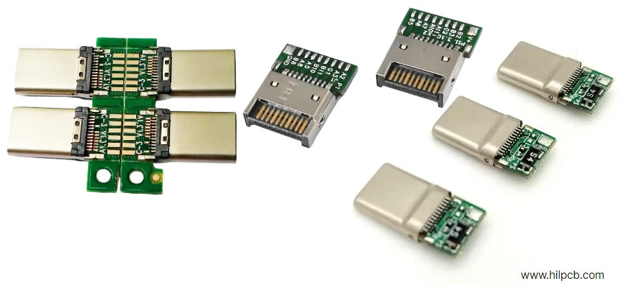
VBUS/GND carry power; D+/D− serve USB 2.0 signaling, while SuperSpeed and USB4 use additional high-speed differential lanes. USB-C configuration-channel (CC) connections support attachment, orientation and PD-related functions. Routing a high-speed PCB requires the selected PHY/controller’s impedance, loss, skew, via and return-path requirements. Define connector/mux/ESD-device transitions and any retimer placement; do not apply one trace-width or length-matching rule to every USB generation.
USB Adapters and Converters
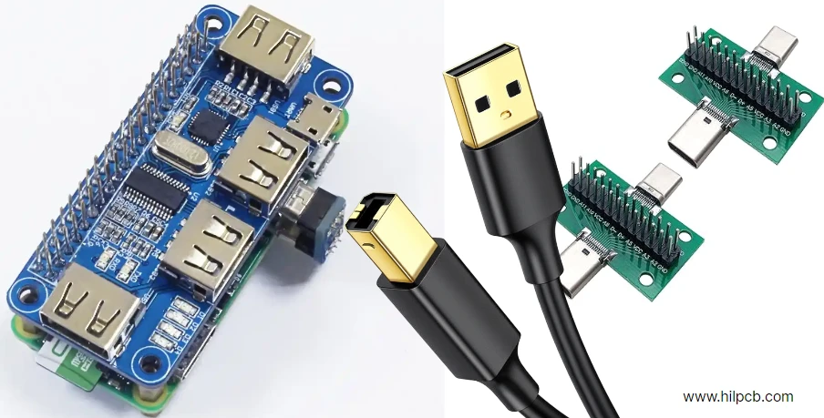
Adapters can change connector form, convert protocols or expose hub/dock functions. Check the actual upstream and downstream capabilities: an adapter cannot create a missing host video mode or USB4 link, and a passive shape change is not a protocol conversion.
Common Types of USB Adapters
- USB-C to USB-A adapters Connect a supported legacy peripheral to a compatible USB-C host. Data rate and power follow the implemented ports, adapter and cable; USB 2.0-only and faster variants exist.
- USB-C to HDMI or DisplayPort adapters Many use a host DisplayPort Alt Mode path, with conversion for HDMI where needed. USB4/Thunderbolt docks may use tunneled display traffic. Check the required display mode and host support; separate USB graphics devices may use drivers instead.
- Multi-function USB-C hubs and docks USB-A, display, Ethernet, card and audio functions share upstream resources. PD pass-through depends on the source, dock, cable and host contract; dock consumption and allocation can reduce power available to the laptop. Do not assume every dock passes 240 W.
- USB-C to Ethernet converters Active bridges can provide 1, 2.5 or 10 GbE in selected products. USB upstream bandwidth, bridge capability, drivers and thermal behavior limit actual network throughput.
- USB-C audio and card readers Digital audio adapters contain a compatible USB audio interface/DAC; passive analog accessories need specific port support. Card-reader performance depends on the card, reader and upstream USB link.
- Protocol and industrial converters Active USB-to-RS-232/RS-485, CAN or other bridges support laboratory and automation interfaces. Specify protocol, voltage levels, isolation/grounding and driver support rather than relying on connector shape.
- USB-C to proprietary power connectors Use an adapter specifically intended for the target equipment, voltage and power negotiation. A passive plug conversion is not proof of correct PD negotiation, polarity or device compatibility.
Active electronics do not automatically confer USB4, Thunderbolt or multi-display capability. External GPUs, NVMe storage and accelerators require the appropriate supported PCIe-tunneling/controller, operating-system and enclosure path, not merely a USB-C socket.
Core Features of Modern USB
- Host/device enumeration with supported class or vendor drivers.
- Hub expansion within address, topology, power and bandwidth limits.
- Compatibility paths for supported older USB functions and connectors.
- PD negotiation where implemented, with power and data roles defined separately.
- USB4 protocol tunneling, including DisplayPort/PCIe where the product supports them.
- A common USB-C form factor whose actual data, display and power capabilities must be stated.
Why USB Replaced Many Serial and Parallel Connections
- Speed and function: Successive generations serve low-speed peripherals through fast storage and display docks. Select the data rate required by the device rather than assuming the fastest connector is needed.
- Compatibility: Standardized classes, hubs and connector families simplify peripheral attachment; industrial serial links and display connectors still serve applications with different needs.
- Mechanical design: Reversible USB-C simplifies insertion, while retention, cycle life, shell anchoring and enclosure support depend on the chosen connector. A 10,000-cycle requirement applies to particular families such as Micro connectors in the legacy USB 3.0 connector compliance document; it is not a universal life claim for all USB ports or their solder joints.
Frequently Asked Questions
What is the difference between USB-C and Thunderbolt ports?
USB-C describes the connector. A USB-C port may implement USB 2.0, USB 3.2, USB4 and/or Thunderbolt capabilities. Thunderbolt 4 provides a 40 Gbps link; Thunderbolt 5 provides 80 Gbps bidirectional bandwidth with optional redistribution to 120/40 Gbps for display-heavy traffic. Actual displays, PCIe devices and data rates still depend on the complete connection.
Can the same USB-C charger power phones, tablets and laptops?
When source and sink support a compatible contract with sufficient power, yes. Check the supported voltage/current profiles and cable rating, not wattage alone. A lower-power source may charge slowly or fail to support the required operating mode. PD negotiation is separate from the device's battery charging and protection functions.
Why can a USB-C cable charge well but transfer data slowly?
Power rating and data capability are separate. A USB-C cable can support high-power charging while carrying only USB 2.0 data. An electronic marker identifies supported cable characteristics where required; its presence alone does not establish a high data rate or video mode. USB-IF’s cable guidance separates power and data markings and notes that a certified cable cannot add capabilities to a device.
Is USB4 faster than USB 3.2?
Its higher-rate implementations are: USB 3.2 reaches 20 Gbps, USB4 Version 1.0 supports up to 40 Gbps, and Version 2.0 adds up to 80 Gbps plus optional asymmetric operation. The negotiated link and workload determine the result; sharing a link with displays or using a slower cable/device can limit throughput.
Will USB-C replace every other port?
It combines several useful functions, but adoption and requirements vary. Ethernet, HDMI/DisplayPort, industrial buses and proprietary connectors continue to serve their respective applications. Specify the needed electrical and mechanical interface rather than assuming future universal replacement.
Manufacturing a USB Interface PCB
HilPCB's high-speed PCB route includes 75/75 µm standard and eligible advanced 50/50 µm geometry, with standard ±10% and advanced ±5% controlled-impedance options and TDR. These are construction options confirmed for the released stackup; they do not certify a USB4 or Thunderbolt channel. USB 2.0 controllers, high-speed docks and high-power ports impose different manufacturing needs.
SMT assembly and through-hole assembly can address the connector/package mix, shell anchoring, board support and inspection access. A pilot test plan can include connector orientation/attachment, safe power-path checks, agreed PD role/profile tests and data-link checks with identified firmware, peers, cables and fixtures. Specify any advanced channel/VNA or compliance testing separately.
Send the fabrication files, stackup, BOM/placement and connector mechanical drawing with the PHY/PD-controller part numbers, required data/display modes and power contracts. Include approved cable/peer configurations, test limits, quantities and record needs. HilPCB can quote fabrication, turnkey sourcing and assembly and the agreed inspection/test package against those requirements.