
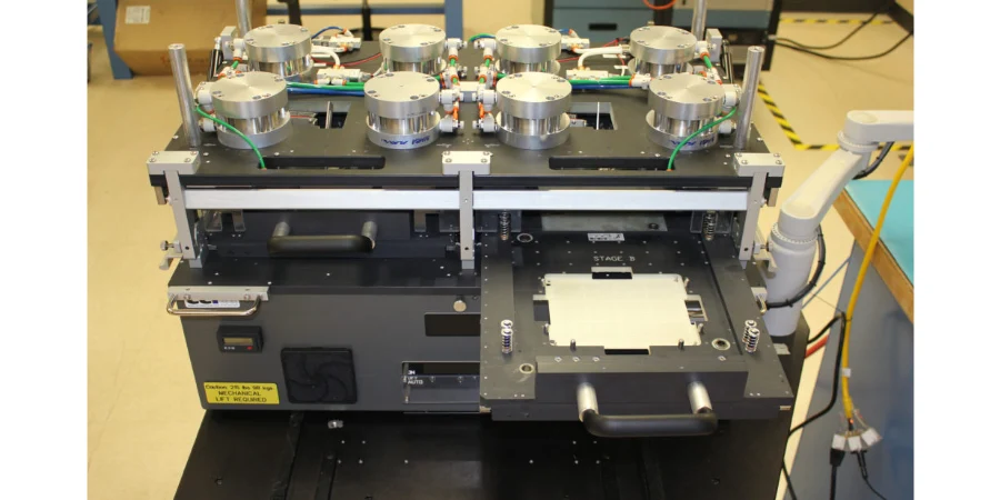
Functional-circuit testing (FCT) powers an assembled board and checks specified behavior using a documented stimulus, fixture, firmware, limits, and test program. It can verify a sensor reading, communication transaction, power output, or other required function. Coverage depends on what the test stimulates and observes; passing a short production sequence does not establish every operating condition or lifetime failure mode.
HilPCB supports programming, accessible electrical tests, boundary scan, and FCT through its assembly route, with customer data, fixtures, coverage, and result format agreed for the order. Define the board functions and acceptance questions first, then select the station and evidence package.
Functional Test and Specialized Material Measurements
Board material affects fixture support, thermal behavior, interfaces, and the relevant characterization. It does not automatically determine the FCT sequence or require a tester “calibrated for ceramic” rather than for the measured quantity.
Match the measurement to its purpose:
- High-frequency behavior: A Rogers PCB assembly may need defined RF gain, output, receiver, or link checks. S-parameter characterization is a separate selected measurement with its own ports, frequency band, fixture, calibration plane, and limits.
- Thermal behavior: Ceramic PCB validation can include temperature or heat-path measurements under specified load and cooling. Thermal cycling is a qualification or screening activity when called for, rather than an inherent step in every FCT.
- Dielectric properties: Supplier data or dedicated characterization supports the approved PTFE construction. A powered functional pass does not directly measure bulk dielectric loss.
- Power electronics: For metal-core boards, define output/load and temperature checks, and applicable circuit-to-core insulation tests. Functional testing does not directly establish dielectric thermal conductivity.
- Environmental stress: Temperature, humidity, or vibration exposure needs a separate method, specimen configuration, limits, and provider; specify whether functions are monitored during exposure or checked afterward.
- Parametric behavior: Measure the required timing, current, voltage, consumption, or signal-quality parameters with appropriate bandwidth, accuracy, and loading.
- Intermittent failures: Specify the monitored signals, sample rate, triggers, duration, and logging needed to capture the suspected event. Continuous logging cannot guarantee capture of every intermittent fault.
- Custom stimulus: Exercise the defined inputs, loads, modes, communication transactions, startup, and recovery states required for release.
- Impedance: Coupon TDR or a selected board measurement supports controlled-impedance fabrication; it is distinct from confirming a populated board's function.
Confirm which measurements belong in production FCT and which are engineering characterization or qualification. This prevents a routine test price or cycle time from silently including a separate laboratory program.
Complex Assembly Architecture Testing Solutions
Production volume and fixture choice: A repeat design may justify dedicated custom test fixtures, automation, and parallel test. Prototypes may start with cables, adapters, or a configurable bench station, but still need reliable connections, board support, power sequencing, and a repeatable procedure. Low quantity does not remove fixture or engineering work. Compare development cost, loading time, test time, contact maintenance, debug, and accepted-unit quantity when choosing a route.
Rigid-flex and dense assemblies: Support a rigid-flex assembly in its specified test or installed shape and protect connectors and bend regions. Dynamic flex testing is an available advanced rigid-flex route when specified; do not assume every FCT bends the board while probing it. HDI assemblies may use boundary scan where device support, the chain, BSDL files, and netlist provide access. Physical probes and boundary scan each have coverage limits. XJTAG's technical FAQ describes the device and design-data requirements.
Multilayer and power-domain checks: A multilayer board is tested through accessible nets and functions, not by separately operating every internal layer. Bare-board electrical test and fabrication evidence address their own connectivity and construction questions. Assembly FCT can check specified rails, loads, startup, interfaces, and responses; ground-plane geometry, EMC, and full PDN characterization need the relevant design or measurement evidence.
Manufacturing Process Integration and Quality Control Systems
Connect the test station to the released build and the disposition of each result.
Key functional testing controls:
- Station checks: Verify the station with suitable references at a risk-based interval and after relevant changes; formal instrument calibration and a daily reference-board check are different activities.
- Environment: Set temperature, humidity, ESD, and warm-up requirements from the device and measurement needs. Record the conditions needed to keep the selected measurement within its required uncertainty and repeatability.
- Program validation: Confirm operation with known-good units and suitable known faults, simulations, or safe fault insertion. Record what each check can and cannot detect.
- Process monitoring: Trend suitable parameters with consistent configuration, sampling, and reaction rules. Control-chart limits and product acceptance limits have different purposes.
- Failure classification: Separate connection/fixture errors, program issues, and genuine board failures before assigning repair or process action.
- Correlation: Compare stations and repeat measurements, and investigate discrepancies with downstream system tests. Correlation does not mean the tests cover identical functions.
- Data: Define serial or lot identity, board/firmware/program revision, measurements, limits, outcome, rework/retest history, record format, and retention.
- Maintenance: Control probe wear, cables, connectors, fixtures, instrument suitability, program changes, and post-maintenance verification.
- Design data: The Gerber viewer can help inspect visible fabrication layers. Testability review also needs schematics, netlist, BOM, layout/access information, firmware, interfaces, and the functional specification; Gerber inspection alone does not verify coverage.
Test Program Development and Optimization Strategies
Advanced Test Vector Generation and Simulation
Start from a coverage list: function or requirement, stimulus, measured response, limit, settling or observation time, failure code, and stored result. Assign test-program and fixture ownership, version control, source-file handoff, and approval authority. Simulation can support development, but the resulting sequence must be checked on representative hardware with the actual firmware and fixture.
A communication loopback, for example, checks the exercised path and mode; it does not automatically establish receiver sensitivity, every external cable condition, or interface conformance. Record excluded functions and residual coverage gaps so the production pass has a clear meaning.
Parametric Testing and Statistical Analysis
Retain numerical results when they answer an engineering or process question, with units, measurement conditions, and limits. Consider instrument uncertainty, fixture loss or resistance, loading, repeatability, and the agreed decision rule near a limit. Trend comparable data; a firmware or test-program change can alter a distribution without any assembly drift.
Production throughput includes handling, connection, programming, settling, measurement, reset, and any required retest—not just the instrument acquisition time. Compare setup amortization and test cost per accepted unit at the planned volume, including the work needed to investigate failures. NI's functional-test overview discusses modular stations, reuse, and production-test considerations.
Debug and Diagnostic Capabilities
Useful failure records identify the test step, expected and measured response, station and program revision, board identity, and relevant logs. These narrow the investigation; one failed measurement may still have several possible causes. Check the fixture and reproduce the failure before repair, then apply the approved rework and retest rules.
For SMT assembly, correlate FCT with visible inspection, selected X-ray, accessible electrical checks, and process records where useful. Preserve first-fail and retest history rather than overwriting it with the final pass. This helps distinguish a repaired board from a station contact problem and supports verified corrective action.
HilPCB Assembly and Functional-Test Handoff
HilPCB also engineers dynamic-flex fixture contacts and can provide chamber testing, automated handling and environmental FCT for scoped builds, with troubleshooting support when results fall outside the agreed limits. Fixture contact design, chamber profile and handling coverage are defined for the board and test plan.
HilPCB's SMT/THT and turnkey assembly routes connect approved sourcing, assembly, programming, and selected electrical/functional tests. Standard SMT placement capability includes 0201 components and 0.4 mm pitch, with finer packages reviewed separately. First-article, profile, selected SPI/AOI/X-ray, programming, ICT/FCT, and lot or serial records are available within the quoted scope. Agree the required record package for first-article and production release during quotation.
Send the BOM/AVL/CPL and fabrication package, schematic/netlist, board revision, firmware/programming files, functional specification, interfaces, required loads, and test-point/connector access. Provide fixtures or define who develops and owns them. Identify any RF, thermal, environmental, isolation, or specialist measurements separately, with methods and limits.
Include quantity/build stage, target throughput, allowed rework/retest, calibration or station-correlation requirements, record format/retention, and the first-article approval process. HilPCB can review the compatible assembly and test route, resolve readiness items, and quote development/setup, production testing, and required records. Once assembly is complete and the agreed fixture and program are ready, functional-test validation is available in 24–48 hours; other FCT schedules depend on readiness and component supply.
Common Questions
What makes functional testing different from in-circuit testing?
FCT checks specified powered behavior through defined inputs, loads, firmware, and measured outputs. ICT checks accessible electrical features and components within its coverage. They can complement one another; neither method automatically covers every assembly fault or use condition.
How does board material affect the test plan?
Material and construction can change fixture support, thermal conditions, interfaces, and required characterization. The measured quantity determines instrument calibration. A functional pass alone does not measure bulk Dk/Df, thermal conductivity, or complete environmental qualification.
What functional testing supports high-frequency applications?
Define the required RF or link behavior, band, ports, mode, fixture, calibration plane, limits, and records. Selected VNA/S-parameter or other RF measurements may be included when scoped; coupon impedance, channel characterization, and powered functionality remain different evidence.
Can functional testing accommodate prototypes?
Yes, a configurable bench setup or dedicated fixture can support a prototype, depending on access and requirements. Fixture design, programming, debugging, components, and approval determine readiness and lead time; define them during quotation.
How do environmental factors affect test accuracy?
Temperature, humidity, vibration, warm-up, and fixture conditions can affect measurements or the device. Specify the operating and measurement conditions needed for repeatability. Separate routine station controls from an environmental stress test or qualification program.
What quality standards govern functional testing programs?
Use the applicable product requirements, component data, and approved functional-test plan. IPC workmanship and J-STD-001 soldering requirements do not replace numerical functional limits, coverage, or the test procedure.
What do PCBA functional testing and board functional test mean?
They describe testing the specified functions of an assembled board. The tester or station supplies the defined stimulus and measures the response; the fixture provides repeatable connections and support. The released procedure defines what its pass result means.