
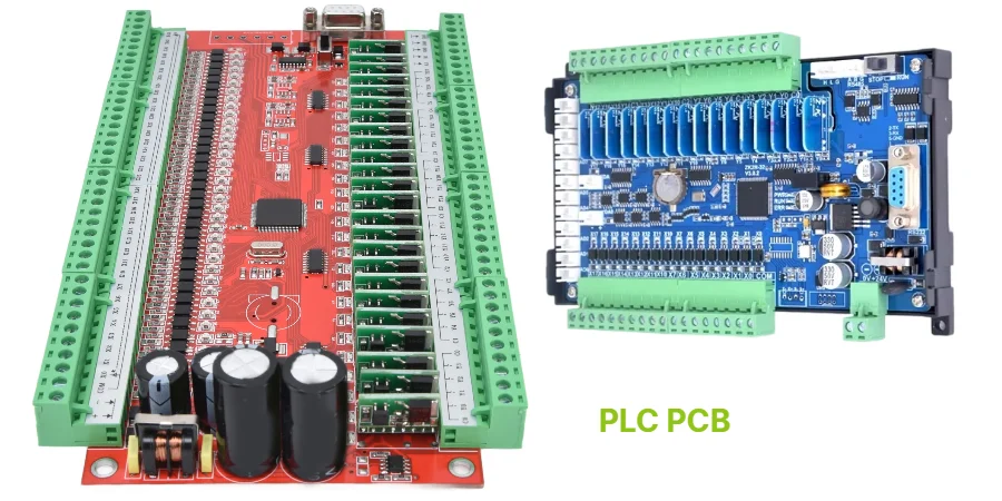
A control panel PCB is the board-level interface between industrial logic, operators, field devices, power distribution, and communication networks. It may sit behind a push-button panel, inside an HMI, in a remote terminal unit, or as part of a larger machine-control cabinet. In every case, the board must keep working while exposed to electrical noise, temperature cycling, vibration, dust, humidity, service handling, and long production schedules.
That makes control panel PCB design different from ordinary embedded hardware. The goal is not only to route signals and power. The PCB has to support maintainable wiring, safe isolation, stable industrial communication, predictable diagnostics, and repeatable manufacturing.
This guide explains the engineering decisions that matter most for industrial automation boards, including rugged display interfaces, push button panels, SCADA gateways, remote terminal PCBs, waterproof PCB protection, industrial Ethernet, functional safety boundaries, and production test planning.
Key Takeaways
- A control panel PCB supports automation reliability, but it does not by itself certify the whole machine, cabinet, PLC, HMI, or safety system.
- Early architecture should separate field wiring, power switching, analog sensing, communication ports, safety-related circuits, and operator interfaces.
- Industrial Ethernet and RS-485/CAN interfaces need controlled routing, isolation, surge/ESD protection, and connector planning before layout is frozen.
- Functional safety requires a system-level risk assessment; the PCB can support separation, diagnostics, traceability, and redundant channels, but it cannot replace IEC 61508, ISO 13849, or machine-level validation.
- Waterproof or rugged designs depend on enclosure, gasket, connector, coating, potting, and process controls, not PCB material alone.
- The most useful RFQ package includes schematic, Gerbers, stackup, BOM, expected environment, insulation rules, coating/potting notes, firmware/programming needs, and test requirements.
In This Guide
- Where control panel PCBs fit in automation architecture
- Industrial I/O and operator-interface design
- Power integrity and protection for cabinet electronics
- Industrial Ethernet, SCADA, and remote terminal connectivity
- EMC, grounding, and isolation strategy
- Harsh-environment protection: coating, potting, and enclosure interaction
- Functional safety boundaries for control panel PCBs
- Manufacturing, testing, and traceability
- Common failure modes
- Cost drivers
- RFQ checklist
- FAQ
Where Control Panel PCBs Fit in Automation Architecture
Industrial control panels combine multiple hardware roles. Some boards are simple operator interfaces with LEDs, key switches, and push buttons. Others include microcontrollers, isolated I/O, relay outputs, industrial Ethernet, analog acquisition, display backlights, memory, local diagnostics, and remote connectivity.
A practical control panel PCB architecture normally includes several zones:
| PCB zone | Typical circuits | Key design concern |
|---|---|---|
| Field wiring interface | Terminal blocks, M12 connectors, relays, optocouplers, digital inputs | Surge, miswiring, isolation, serviceability |
| Operator interface | Push buttons, LEDs, encoders, touch keys, display connectors | ESD, debounce, lighting consistency, mechanical alignment |
| Processing and logic | MCU, MPU, FPGA, memory, watchdog, real-time clock | Firmware update access, diagnostics, power sequencing |
| Communication | Ethernet PHY, RS-485, CAN, wireless module, USB service port | EMC, isolation, impedance, connector shielding |
| Power conversion | 24 VDC input, DC/DC converters, LDOs, fuses, TVS, reverse-polarity protection | Transients, thermal rise, startup behavior, safety spacing |
| Safety-related channels | E-stop input, guard switch input, safety relay interface | Separation, redundancy, diagnostics, documented limits |
The PCB should be designed around the real cabinet and wiring environment. A board intended for a clean indoor HMI is not the same as a remote terminal PCB mounted near pumps, conveyors, compressors, outdoor cabinets, or washdown equipment.
Industrial I/O and Operator-Interface Design
Industrial control panels usually connect to people and field devices at the same time. That combination creates mechanical, electrical, and safety challenges.
Push Button Panel PCB
A push button panel PCB may look simple, but it must handle repeated mechanical actuation, ESD from operators, cable noise, wet or dusty hands, long harnesses, and service replacement.
Important layout practices include:
- use defined keepout areas under mechanical actuators and bezels
- reinforce high-stress connectors with through-hole pins, mounting holes, or mechanical support
- add ESD protection near external buttons, encoders, and service ports
- route button inputs away from relay coils, motor-control wiring, and switching converters
- use hardware debounce or firmware filtering when long wires create bounce/noise risk
- keep indicator LED current paths and button-sense paths separated when possible
For boards with emergency stop, guard, or two-hand-control functions, the PCB must be designed according to the safety architecture. Do not treat a safety input as an ordinary push button unless the system risk assessment permits it.
Rugged Display PCB
A rugged display PCB behind an HMI must support display power, backlight current, touch sensing, data interfaces, sealing, and EMC in one compact assembly. Display problems often come from power ripple, cable radiation, ESD at the front panel, or heat concentration behind the screen.
Good engineering practices include:
- separate backlight power from touch and display data signals
- add local filtering for LCD bias rails, touch-controller rails, and backlight drivers
- protect touch and front-panel signals from ESD events at the connector or entry point
- define connector locking method, cable bend radius, and strain relief early
- review thermal behavior with the display, enclosure, gasket, and backlight running together
If the front panel is sealed, condensation and pressure equalization should be considered at the enclosure level. A conformal-coated PCB alone does not create a waterproof HMI.
Power Integrity and Protection for Cabinet Electronics
Many industrial boards use 24 VDC nominal power, but the real input can include voltage dips, brownouts, inductive kick, reverse polarity, surge, ESD, conducted noise, and wiring mistakes. The control panel PCB has to remain predictable under these conditions or fail safely.
Input Protection Stack
A robust input section may include:
| Function | Typical implementation | PCB design note |
|---|---|---|
| Reverse-polarity protection | Diode, ideal diode controller, protected MOSFET | Check thermal loss at rated current |
| Overcurrent protection | Fuse, resettable fuse, eFuse, current-limited DC/DC | Define coordination with upstream protection |
| Surge and transient suppression | TVS diode, MOV, gas discharge tube in higher-energy systems | Keep surge current loops short and wide |
| EMI filtering | Common-mode choke, differential filter, feedthrough capacitors | Do not let noisy return current bypass the filter |
| Hold-up or brownout tolerance | Bulk capacitance, supervisor, firmware state handling | Validate startup and dropout behavior |
Power protection should be matched to the expected installation category, cable length, supply source, and cabinet grounding. Oversized protection parts can create thermal and cost issues; undersized parts can fail during surge or miswiring events.
Power Distribution and Thermal Planning
A control panel PCB may drive relays, indicator lamps, small solenoids, communication ports, and embedded processors from the same board. That often requires multiple rails.
Practical rules:
- keep high-current relay, solenoid, and lamp paths away from low-noise analog and communication circuits
- use wide copper pours and clear current-return paths for output loads
- place flyback diodes, TVS devices, or snubbers close to inductive loads or connectors
- check temperature rise on DC/DC converters, relay drivers, terminal blocks, fuses, and high-current traces
- consider heavy copper PCB only where current density and temperature rise justify it
- use high-Tg PCB when enclosure temperature, reflow exposure, or long thermal cycling makes standard material marginal
Industrial Ethernet, SCADA, and Remote Terminal Connectivity
Automation systems commonly combine industrial Ethernet, serial fieldbus, local I/O, and SCADA reporting. The PCB must protect each interface from cabinet noise while preserving signal quality.
Industrial Ethernet PCB Design
Industrial Ethernet ports may support PROFINET, EtherNet/IP, EtherCAT, Modbus TCP, or standard Ethernet-based service access. These protocols differ at the system level, but the PCB still needs sound Ethernet physical-layer design.
| Interface item | PCB recommendation |
|---|---|
| Differential pairs | Route as controlled-impedance pairs with continuous reference planes |
| Magnetics | Place close to the connector or according to PHY/vendor guidance |
| Common-mode choke | Use where EMC and system architecture require it |
| Chassis/functional ground | Define shield termination intentionally, not by accidental copper contact |
| ESD protection | Place near external connector and select low-capacitance parts for Ethernet |
| Isolation boundary | Respect spacing around transformers, digital isolators, and connector shields |
| Return path | Avoid plane splits under high-speed pairs unless the stackup supports a controlled transition |
For multilayer PCB designs, stable reference planes make Ethernet routing, EMC control, and repeatable fabrication easier than forcing the interface onto a two-layer board.
SCADA PCB and Gateway Functions
A SCADA PCB or gateway board often aggregates data from PLCs, RTUs, sensors, drives, and local operator panels. It may include Ethernet, RS-485, CAN, digital inputs, analog inputs, storage, and cellular or Wi-Fi modules.
Key design considerations:
- isolate fieldbus ports when long cables or separate ground potentials are expected
- include termination, biasing, and protection options for RS-485 networks
- provide service access for firmware updates and configuration recovery
- protect nonvolatile memory from corruption during brownout or interrupted updates
- include status LEDs, test pads, and diagnostic points that technicians can understand in the field
- avoid placing RF modules next to relay coils, switching converters, or unshielded high-current wiring
Remote Terminal PCB
A remote terminal PCB may be installed in water treatment plants, pipelines, outdoor cabinets, pumping stations, or distributed machine cells. These boards often need wider temperature range, conformal coating, surge tolerance, and low-maintenance diagnostics.
Design priorities include:
- low-power modes when remote supply or backup battery is used
- secure connectors with clear labeling for field technicians
- surge-rated I/O and communication protection for long cables
- watchdog and safe restart behavior after power interruptions
- local logging or buffering when SCADA communication is temporarily unavailable
EMC, Grounding, and Isolation Strategy
Industrial cabinets are noisy. Motors, variable frequency drives, contactors, relays, welders, heaters, and long cable runs can create conducted and radiated disturbances. The PCB cannot solve every cabinet-level EMC problem, but it can avoid becoming the weak point.
Zoning and Return Paths
The layout should define electrical zones before placement starts:
| Zone | Keep away from | Common controls |
|---|---|---|
| Analog inputs | Relay coils, DC/DC switch nodes, Ethernet magnetics | Guarding, filtering, stable reference, shielded connector strategy |
| Digital logic | High-current outputs and inductive loads | Local decoupling, clean ground return, watchdog |
| Power switching | Touch/display cables, analog front ends | Compact loops, snubbers, thermal copper, shielding if needed |
| Communication ports | Unprotected field wiring and high-voltage areas | ESD, isolation, controlled routing, connector shielding |
| Safety-related channels | Noisy or non-safety circuits that can create common-cause faults | Physical separation, independent routing, diagnostics |
A “split ground” label is not enough. Engineers should define where currents return, where shields terminate, where isolation barriers exist, and how the PCB bonds to the metal enclosure or DIN rail.
Isolation and Creepage/Clearance
Industrial control boards often mix SELV/PELV control circuits, mains-derived power, relay contacts, motor-control signals, and communication interfaces. Spacing rules depend on voltage, pollution degree, altitude, insulation category, coating, material group, and the applicable product standard.
The PCB package should clearly call out:
- working voltage and transient overvoltage assumptions
- pollution degree and installation environment
- creepage and clearance requirements between domains
- slots, cutouts, or barriers used to increase spacing
- whether conformal coating is relied on for protection or only environmental durability
- Hi-Pot or insulation-resistance test requirements
A PCB supplier can help manufacture the spacing and test features, but the equipment manufacturer must define the insulation requirements.
Harsh-Environment Protection: Coating, Potting, and Enclosure Interaction
A waterproof PCB is rarely waterproof by PCB design alone. The protection level comes from the full assembly: enclosure, gasket, connector, cable gland, coating, potting, venting, and test method.
Conformal Coating
Conformal coating can help protect against humidity, dust, condensation, mild chemical exposure, and surface contamination. It is common for control panel PCBs installed in dusty, humid, or lightly corrosive environments.
Design notes:
- define coating type, thickness target, keepout areas, and inspection method
- keep test pads, connectors, trim parts, and programming headers compatible with masking or removable protection
- avoid sharp component shadows that create coating voids
- confirm coating compatibility with labels, plastics, relays, switches, and connectors
- validate adhesion after cleaning, flux residue control, and thermal cycling
IPC-CC-830 qualification helps frame conformal coating material requirements, but the coated PCBA still needs process validation in the actual product environment.
Potting and Encapsulation
Potting gives stronger protection but makes inspection, repair, and thermal analysis harder. It can be useful for remote terminal modules, vibration-prone boards, outdoor sensors, or sealed industrial electronics.
Before potting, freeze:
- resin chemistry and supplier
- mix ratio, degassing, cure time, and cure temperature
- component compatibility and maximum temperature exposure
- inspection method before and after potting
- how heat will leave the assembly
- whether the potted unit can be reworked or must be discarded after failure
Full potting is not automatically better. Partial potting or selective encapsulation may provide the right balance between protection, serviceability, and thermal performance.
Enclosure and IP Rating Boundary
Ingress protection is normally an enclosure-level rating. The PCB can support it through connector placement, drainage awareness, coating, corrosion-resistant finish, and mechanical alignment, but the final IP rating depends on the assembled enclosure test.
For washdown, outdoor, or dusty installations, review:
- gasket compression and service replacement
- cable gland sealing
- condensation path and pressure equalization
- connector orientation and water traps
- corrosion risk near exposed metal and dissimilar materials
- label readability and maintenance access after environmental exposure
Functional Safety Boundaries for Control Panel PCBs
Functional safety is a system discipline. A control panel PCB may support safety-related functions, but it does not create a Safety Integrity Level or Performance Level by itself.
A safety-related PCB design may include:
- redundant input channels for emergency stop, guard switch, or safety interlock signals
- physical separation between redundant paths to reduce common-cause faults
- diagnostic test pulses or monitored input circuits
- independent power and ground paths where required by architecture
- watchdogs, brownout detection, safe-state outputs, and fault logging
- clear documentation for traceability and validation
However, the target SIL or PL must come from risk assessment, architecture, component reliability data, diagnostic coverage, systematic capability, software behavior, and validation of the complete safety function.
| Safety topic | PCB can support | PCB cannot prove by itself |
|---|---|---|
| Redundant channels | Layout separation and independent routing | System diagnostic coverage |
| Safe-state outputs | Output driver layout and protection | Correct machine stopping behavior |
| E-stop interface | Connector, filtering, spacing, diagnostics support | Compliance of the entire emergency-stop function |
| Fault detection | Test points, status circuits, watchdog routing | Final SIL/PL claim |
| Traceability | Lot records, inspection, test reports | Complete safety lifecycle compliance |
For safety-related assemblies, share the safety concept with the PCB/PCBA manufacturer early. It affects spacing, routing separation, connector selection, test access, inspection records, and change control.
Manufacturing, Testing, and Traceability
A control panel board often combines SMT logic, through-hole connectors, relays, terminal blocks, displays, LEDs, and sometimes hand-installed mechanical parts. Manufacturing success depends on whether the board was designed for repeatable assembly and testing.
DFM and DFT Review
Before fabrication, review:
- copper balance and panelization for large boards
- connector clearances and insertion direction
- wave/selective soldering access for through-hole parts
- relay and terminal-block mechanical support
- coating/potting keepouts and masking requirements
- test-pad access after assembly and enclosure installation
- programming header access and firmware serialization
- barcode or QR code position for traceability
Recommended Test Flow
| Stage | Typical checks | Purpose |
|---|---|---|
| Bare PCB fabrication | Electrical test, impedance coupons if required, dimensional inspection | Catch opens, shorts, and fabrication errors before assembly |
| SMT assembly | SPI, AOI, reflow profile control | Confirm solder paste and placement quality |
| Through-hole assembly | Selective solder / wave solder inspection, fillet inspection | Verify connector, relay, and terminal-block joints |
| X-ray inspection | BGA, hidden joints, selected high-risk solder joints | Detect hidden voiding, shorts, or insufficient wetting |
| Programming | Firmware load, configuration, serialization | Create traceable product identity |
| ICT or flying probe | Opens, shorts, component values, basic power checks | Catch assembly defects before functional testing |
| Functional test | I/O states, communication ports, display, buttons, relays, analog inputs | Verify the board as a working control-panel assembly |
| Environmental or stress screening | Temperature, humidity, vibration, power cycling as needed | Validate high-risk applications or production release |
For turnkey assembly, the most effective approach is to align fabrication, assembly, programming, functional test, packaging, and traceability under one controlled plan.
Common Failure Modes
| Failure mode | Likely cause | Prevention strategy |
|---|---|---|
| False input triggering | Long wires, poor filtering, weak ESD design, noisy ground return | Input filtering, shielding, debounce, robust return path |
| Ethernet communication dropouts | Poor impedance, weak shield strategy, noisy power, connector ESD | Controlled routing, magnetics placement, ESD, EMC review |
| Relay or terminal overheating | Undersized copper, high contact resistance, poor solder joint | Current-density review, heavy copper if needed, thermal validation |
| Corrosion or leakage | Humidity, flux residue, coating voids, chemical exposure | Cleaning control, coating validation, corrosion-resistant layout |
| Display flicker or reset | Backlight current transients, power droop, EMI coupling | Local filtering, rail sequencing, power integrity review |
| Coating delamination | Poor cleanliness, incompatible material, inadequate cure | Material compatibility check and process validation |
| Safety-channel common-cause fault | Redundant paths routed too close or share vulnerable components | Physical separation, independent routing, documented safety layout |
| Field service confusion | Poor labeling, inaccessible connectors, missing diagnostics | Clear silkscreen, status LEDs, keyed connectors, service test points |
Cost Drivers
Control panel PCB cost is usually driven by the reliability and integration choices rather than board area alone.
| Cost driver | Why it increases cost | How to control it |
|---|---|---|
| Layer count | More planes, routing density, communication interfaces | Freeze architecture and stackup early |
| Heavy copper | Higher material and processing complexity | Use only where current density requires it |
| Isolation spacing and slots | Larger board area and routing constraints | Define voltage domains early |
| Coating or potting | Extra material, masking, cure, inspection, rework limits | Use selective protection when possible |
| Industrial connectors | Mechanical reliability and field wiring requirements | Standardize connector families across products |
| Functional test fixture | Upfront tooling and engineering | Design test access before layout completion |
| Traceability requirements | Serialization, MES setup, records, reporting | Define data fields before pilot build |
| Environmental validation | Time, samples, fixtures, lab testing | Match tests to actual operating risk |
The lowest unit price is rarely the lowest lifecycle cost for industrial controls. Rework, field service, downtime, and replacement logistics often dominate after deployment.
RFQ Checklist for Control Panel PCB and PCBA
Send these items when requesting a quote or DFM review:
- Gerber, ODB++, or IPC-2581 files
- Schematic and netlist if DFM/DFT support is requested
- BOM with approved manufacturers and alternates
- PCB stackup, copper weight, impedance requirements, and material preference
- Operating voltage domains and required creepage/clearance rules
- Expected environment: indoor/outdoor, humidity, dust, chemicals, washdown, vibration, temperature range
- Connector and enclosure constraints, including mounting-hole tolerances
- Coating, potting, masking, or sealing notes
- Programming, serialization, and firmware-loading requirements
- ICT, flying probe, functional test, communication test, or Hi-Pot requirements
- Acceptance class or inspection standard requirements
- Packaging, ESD, labeling, and traceability expectations
- Pilot quantity, production forecast, and target delivery schedule
A complete RFQ reduces assumptions. For industrial control panels, missing environment and test information is often more dangerous than missing board dimensions.
Standards and Compliance Context
The following standards are commonly relevant to industrial control equipment, but their applicability depends on the finished product, installation region, and intended use:
- IEC 60204-1: electrical equipment of machines
- UL 508A: industrial control panels in the U.S. context
- IEC 61131-2: PLC, PAC, remote I/O, HMI, and industrial control equipment requirements and tests
- IEC 61000-6-2 / IEC 61000-6-4: generic EMC immunity and emissions for industrial environments when no dedicated product standard applies
- IEC 60529: enclosure ingress protection rating framework
- ISO 13849-1 and IEC 61508: functional safety design context for safety-related control systems
- IPC-A-610 and IPC J-STD-001: electronic assembly acceptability and soldering workmanship
- IPC-CC-830: qualification and conformance requirements for conformal coating materials
A PCB or PCBA can support these requirements through layout, materials, spacing, documentation, process control, and test access. Final compliance belongs to the completed equipment and its validated use case.
How HILPCB Supports Industrial Control Panel PCB Projects
HILPCB supports industrial automation hardware from prototype through production with PCB fabrication, assembly, DFM review, material selection, coating/potting coordination, test planning, and traceability.
Typical support includes:
- Multilayer PCB manufacturing for industrial Ethernet, HMI, and mixed-signal control boards
- High-Tg PCB and heavy copper PCB options for thermal and current-handling needs
- SMT assembly and through-hole assembly for connectors, relays, terminals, displays, and operator-interface hardware
- Turnkey assembly for component sourcing, PCBA, programming, functional testing, and packaging
- Prototype and small-batch support before production tooling is locked
For best results, involve the manufacturing team before the enclosure, wiring layout, safety spacing, coating plan, and test strategy are frozen.
Conclusion
A reliable control panel PCB is a systems component, not just a circuit carrier. It has to support field wiring, operator input, industrial communication, power protection, environmental durability, diagnostics, and manufacturing traceability in one coordinated design.
The strongest designs start with clear boundaries: what the PCB controls, what the enclosure protects, what the safety system requires, what the communication network expects, and what the production test must prove. When those boundaries are defined early, the PCB can be manufactured and assembled with fewer surprises, better repeatability, and lower field risk.
HILPCB helps industrial automation teams turn that plan into manufacturable boards and PCBAs for control panels, rugged displays, push-button panels, SCADA gateways, remote terminals, and waterproof industrial electronics. When your design files, environment requirements, and test plan are ready, request a quote for review.
FAQ
Is a control panel PCB the same as a PLC board?
Not always. A control panel PCB may be an operator interface, I/O board, communication gateway, display board, relay board, or embedded controller. A PLC board is a specific industrial control device with its own architecture and product requirements.
Can a PCB make a control panel UL 508A compliant?
No. A PCB can support spacing, wiring, protection, labeling, and traceability requirements, but UL 508A applies to the industrial control panel as a completed assembly. The panel builder must evaluate the whole enclosure, components, wiring, protection, and markings.
What makes a waterproof PCB different from a normal industrial PCB?
A waterproof design usually depends on the complete assembly: enclosure, gasket, cable glands, connectors, coating, potting, and test method. The PCB itself can support moisture resistance, but the final ingress rating is normally proven at enclosure level.
Do industrial Ethernet PCBs need impedance control?
Yes, Ethernet differential pairs should be routed with controlled impedance and stable reference planes. The exact tolerance and test strategy depend on data rate, stackup, cable length, connector design, and product requirements.
When should conformal coating be used?
Use conformal coating when the board is exposed to humidity, dust, condensation, mild chemical contamination, or corrosion risk. The coating process should be defined before layout is finalized because masking, inspection, test access, and connector compatibility all matter.
What should be verified before production release?
Verify power input behavior, I/O protection, communication stability, EMC risk, thermal rise, enclosure fit, coating or potting process, programming, functional test coverage, and traceability records. Production release should confirm manufacturability as well as circuit function.