
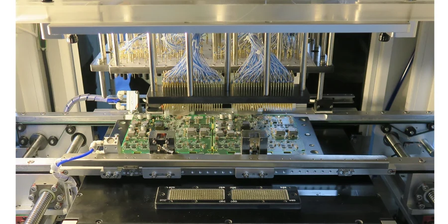
As an automotive reliability engineer responsible for salt fog, thermal shock, and wide-temperature lifetime evaluation, I know that in ADAS and EV power modules, even tiny defects can cause catastrophic outcomes. Across the long journey from prototype to mass production, Fixture design (ICT/FCT) is not just a quality-control step—it is the foundation for meeting automotive standards such as AEC-Q and ISO 26262. A great fixture must validate electrical performance and functional integrity of PCBA with precision and stability under extreme environments—protecting safety and reliability.
This article explains why Fixture design (ICT/FCT) is central in automotive electronics manufacturing, and how it integrates with DFM/DFT/DFA review, SMT assembly, and Traceability/MES to handle high voltage, high frequency, and high heat. From compliance requirements through lifecycle execution, we show how fixtures become the bridge between design validation and scalable production.
From AEC-Q to ISO 26262: fixture design (ICT/FCT) from development to production
In automotive, ECU development must comply with ISO 26262 functional safety and AEC-Q component reliability standards. These standards define not only design validation, but also clear production test expectations. Fixture design (ICT/FCT) turns these requirements into executable, measurable test plans.
ISO 26262 functional safety validation: for systems targeting a given ASIL level—ADAS decision units or EV battery management systems (BMS)—FCT is critical. FCT fixtures must emulate real vehicle conditions: CAN/LIN communications, sensor inputs, and actuator drive. Fixtures must trigger and detect safety-related functions under normal and fault-injection scenarios. For example, an ASIL-D power PCB fixture should simulate over-voltage, under-voltage, and reverse polarity and measure protection response time and states to confirm safety goals.
AEC-Q reliability validation: AEC-Q100 (IC) and AEC-Q200 (passives) require stability under harsh stress (e.g., -40°C to 125°C cycling). While those are component-level standards, PCBA-level verification matters too. ICT fixtures use dense probes on test points to detect solder defects (opens/shorts/wrong parts/polarity) and basic parameters (R/C/L). A strong Fixture design (ICT/FCT) keeps probe contact stable across temperature ranges to avoid false calls due to thermal expansion—providing reliable baseline data for ESS.
At HILPCB, we front-load test strategy so interfaces are reserved from the PCB design stage—laying the foundation for robust fixture design and validation later.
DFM/DFT/DFA review: ensuring test coverage and reliability from the start
If a product cannot be tested effectively, its quality cannot be guaranteed. That’s the value of DFM/DFT/DFA review. During layout, a thorough review is a prerequisite for successful Fixture design (ICT/FCT).
DFT (Design for Testability): ensure all critical nodes can be probed:
- Test-point planning: pad size/pitch/distribution must match ICT probe constraints. For dense designs such as HDI PCB, micro test-point layout becomes especially important.
- Electrical isolation: keep safe distance from high-voltage nets to prevent arcing/breakdown during testing.
- Accessibility: avoid placing test points under large components or shields; ensure vertical, unobstructed probe access.
DFA (Design for Assembly): assembly decisions affect test. For example, placement can block probe access after SMT assembly—a tall connector next to a critical test point may cause unstable contact and false results.
DFM (Design for Manufacturing): ensure the design fits process capability and reduce manufacturing defects. Better pad/solder-mask design improves SMT assembly FPY and reduces the burden on ICT/FCT.
At HILPCB, engineering teams use tools like BOM Viewer and collaborate early with customers to execute deep DFM/DFT/DFA review—eliminating future test obstacles and enabling maximum coverage and stability for Fixture design (ICT/FCT).
🚗 Automotive-grade ICT/FCT fixture lifecycle implementation flow
Follow the IATF 16949 system rigorously and validate stability and data compliance via high-precision compensation and GR&R.
Based on ISO 26262 and AEC-Q, interpret performance metrics and define strict test boundary conditions.
Co-design with R&D to optimize PCB layout, pad spacing, and test access—stabilizing high-frequency interconnects from the source.
Design precision mechanics and low-impedance loops. Simulate LVDS/CAN-FD paths to suppress reflections and crosstalk noise.
Use ESD-grade aluminum frames and high-temp probes; CNC bed-of-nails with ~50 μm alignment for probe insertion.
Develop custom test sequences and connect factory MES for digital traceability of test results.
Run Gage R&R to validate measurement consistency; after line deployment, optimize parameters dynamically using FPY trends.
Environmental and reliability test challenges: temperature/vibration/humidity/salt fog
Reliability tests (thermal cycling, vibration, damp heat, salt fog) challenge the fixture itself.
Wide-temperature adaptability: in -40°C to +125°C thermal shock, fixture materials matter. Plastics can become brittle/soft and lose positioning. Probe spring force changes with temperature and shifts contact resistance. Automotive Fixture design (ICT/FCT) should use specialized materials and high/low-temp probes, plus thermo-mechanical simulation to ensure mechanical stability and electrical contact across the full range.
Vibration and shock: on vibration tables, FCT fixtures must secure DUT and ensure connectors/cables/probes don’t loosen or momentarily open. That requires robust structures and locking/reinforced connections.
Moisture and corrosion protection: for damp heat/salt fog, metal parts need corrosion-resistant treatment (anodizing/passivation). Electrical interfaces require sealing to prevent moisture-induced shorts/leakage. For PCBA with Potting/encapsulation, fixture design must consider how to access internal test points through or around potting—raising requirements on probe type and positioning accuracy.
Process control and traceability: integrating Traceability/MES with fixtures
In automotive electronics, “no traceability” means “no quality.” Traceability/MES is the core of end-to-end quality tracking. Fixture design (ICT/FCT) must act as an intelligent endpoint in that system—not a standalone tool.
Unique ID and data binding: each PCBA receives a unique QR/barcode. A scanner on the fixture reads it and binds all ICT/FCT data (voltages, resistances, pass/fail items, test time, etc.) to the ID and uploads it to the Traceability/MES database.
Process interlocks (poka-yoke): MES controls flow based on test results. If ICT fails, MES locks the unit and prevents it from proceeding to processes like Potting/encapsulation or final assembly, routing it to repair. The fixture must include the communication interface to execute interlock commands.
Big-data analytics and quality improvement: aggregated test data enables SPC and Cpk monitoring to detect systemic drift. For example, if failure rate rises for a component, you can trace supplier lot, timestamp, and related SMT assembly parameters—enabling fast containment and targeted improvement.
Fixture design reminders (key points)
- Signal integrity: for high-speed signals (e.g., SerDes) in ADAS, fixture routing must be impedance-matched to avoid reflections and loss, protecting test fidelity.
- High-voltage safety isolation: for EV power modules (OBC, DCDC), fixtures must meet strict HV safety rules—adequate clearance/creepage between probes/cables/structures and safety interlocks.
- Thermal management: high-power PCBA generates significant heat during FCT. Fixtures should include cooling (fans/heatsinks) to emulate real environments and prevent overheating-induced fails or damage.
- Modularity & maintainability: modular probe blocks enable fast replacement after wear, minimizing line downtime.
Mass production ramp and continuous improvement: closed-loop quality from SMT to final test
The shift from Run@Rate to volume is a final stress test for the entire manufacturing system, including Fixture design (ICT/FCT) maturity.
During pilot builds, ICT/FCT fixtures not only find design/component issues—they validate process stability across SMT assembly, wave soldering, and Selective wave soldering. For example, defect clustering in ICT data can drive stencil aperture or reflow profile optimization.
In volume, fixtures become “sentinels” for process consistency. APQP and PFMEA control plans guide actions, while test data becomes the key input for control execution and 8D problem solving. A well-designed Fixture design (ICT/FCT) produces precise, repeatable data for continuous improvement. With HILPCB Turnkey Assembly, fabrication and assembly test are integrated under one quality system for consistent end products.
High voltage and complex processes: validating Selective wave soldering and Potting/encapsulation
Automotive electronics—especially EV power systems—use special processes that introduce new test challenges.
Selective wave soldering: for Heavy Copper PCB with many through-hole parts (large capacitors, connectors), Selective wave soldering is common. Localized heating can stress nearby SMD parts, so ICT/FCT after soldering is essential. Fixtures must avoid tall through-hole parts while still contacting required nets.
Potting/encapsulation: many ECU use Potting/encapsulation for vibration and humidity/heat robustness. Testing becomes a dilemma: pre-potting tests can’t prove potting didn’t introduce defects; post-potting tests may lose access because test points are covered. Typical solutions:
- Full ICT/FCT before potting to verify functional PCBA.
- Reserve test posts or route test interfaces through connectors so access remains after potting.
- Use special probes/connector modules in Fixture design (ICT/FCT) to mate with those reserved interfaces for final verification.
This requires deep binding among design, process, and test. With experience in SMT Assembly and complex processes, HILPCB provides end-to-end solutions from design through final test.
ICT vs FCT fixture comparison
| Attribute | ICT (In-Circuit Test) fixture | FCT (Functional Test) fixture |
|---|---|---|
| Test goal | Manufacturing defect screening (opens/shorts/wrong parts/values) | PCBA function & performance validation (signals/comm/drives) |
| Design core | Dense probing, electrical isolation, stable contact | Real-environment emulation, SI fidelity, high-voltage safety |
| Process coupling | Immediately after SMT assembly / Selective wave soldering | Multiple stages: pre/post potting, after final assembly |
| Data value | Directly points to process issues (soldering/placement) | Confirms design spec and customer requirements |
| DFT requirement | Very high (many accessible test points) | High (accessible I/O and key signals) |
| System integration | Primarily with Traceability/MES for process control | MES + host software / HIL integration |
Common Questions
Why does automotive fixture design need to be tied to standards like AEC-Q and ISO 26262?
Because automotive test fixtures are not just checking whether a board powers on. They must verify that safety functions, reliability targets, and high-voltage behavior can be measured consistently under realistic fault and stress conditions that align with automotive validation requirements.
Why must DFM/DFT/DFA review happen before ICT and FCT fixtures are finalized?
The article makes clear that test access, probe spacing, isolation distance, and post-assembly accessibility are all decided in design. If those points are not planned early, even a well-built fixture cannot recover lost test coverage or stable contact quality later.
Why is Traceability/MES integration so important for automotive ICT/FCT fixtures?
Automotive programs need every test result bound to a specific unit, process step, and production history. MES-connected fixtures let teams stop failed boards before the next operation, trace drift back to manufacturing conditions, and use test data for real SPC and corrective action.
Why do potting, selective wave soldering, and high-voltage modules make fixture design harder?
Those processes change physical access, electrical safety constraints, and failure modes. Fixtures therefore have to handle tall through-hole parts, preserved access points after potting, and safe high-voltage verification without sacrificing repeatability or damaging the unit under test.
Conclusion
On the road to safer and smarter vehicles, Fixture design (ICT/FCT) is an indispensable “gatekeeper.” It is no longer an isolated production step; it is deeply integrated across the value chain—from DFM/DFT/DFA review through SMT assembly, and into Traceability/MES integration. A strong fixture design embodies engineering insight, process expertise, and quality mindset—detecting potential failure risks and ensuring every ADAS or EV power PCB shipped delivers unmatched reliability and safety.
Choosing a partner like HILPCB with one-stop capabilities—from design optimization to high-reliability fabrication to precision assembly test—means quality assurance from day one. We believe relentless attention to detail is the key to automotive-grade excellence.