
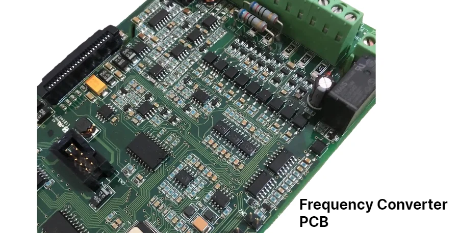
- A frequency counter PCB should be reviewed as a timing-reference system first and a display instrument second.
- The first checks are input frequency range, trigger and conditioning path, timebase quality, counting method, gate-time strategy, and how measurement error will be interpreted.
- Most failures show up as unstable readings, excessive low-signal sensitivity problems, poor high-frequency accuracy, or disagreement between expected and measured resolution.
- Material choice matters on faster front ends, but timebase stability, trigger cleanliness, shielding, and edge-conditioning quality usually dominate accuracy first.
- Prototype success depends on freezing the measurement method early, especially if the project has to cover both low-frequency and higher-frequency use cases.
A frequency counter is a measurement instrument that determines signal frequency by counting events against a known timing reference. On a PCB, that means the board has to preserve a stable timebase, condition the incoming signal cleanly, and route timing-related paths in a way that does not add avoidable jitter, drift, or triggering uncertainty.
Contents
- What to review first on a frequency counter PCB
- Key design and validation rule table
- Early engineering trade-off table
- How timebase, input conditioning, and counting method affect accuracy
- How validation should be planned before prototype release
- What prototype teams should lock down before build
- FAQ
- Next steps
- References
- Author and review
What to review first on a frequency counter PCB
Frequency measurement looks simple until the signal range widens, the signal quality worsens, or the required error budget tightens. At that point, the PCB becomes part of the accuracy problem because the board defines the time reference, trigger cleanliness, and path between the input connector and the counter logic.The first review points are usually:
- what frequency range and signal types the counter is expected to measure
- whether low-frequency, high-frequency, or wide-range measurement methods are required
- what timebase class is needed, such as a standard crystal, TCXO, or OCXO
- how the input signal is limited, amplified, shaped, and triggered before counting
- how measurement error, gate time, and averaging will be handled during validation
If the front end extends into faster RF-like behavior, it is usually worth reviewing high-frequency PCB and high-speed PCB assumptions before layout is finalized.
Key design and validation rule table
| Rule / parameter | What to check first | Why it matters | How to verify | If ignored | | --- | --- | --- | --- | --- | | Timebase quality | Match oscillator stability to the actual accuracy target | The counter cannot be more trustworthy than its reference | Oscillator review and drift budget review | Stable-looking numbers with poor absolute accuracy | | Input conditioning | Confirm limiting, amplification, and trigger shaping for the real signal family | Weak conditioning creates false counts or missed counts | Front-end review and trigger-threshold test plan | Readings jump or disappear under realistic signals | | Counting method fit | Choose period, gated counting, or reciprocal methods to match the range | Different methods behave differently across low and high frequencies | Measurement-method review and expected error review | Good results only in a narrow part of the range | | Gate time and averaging | Define how long the instrument will observe the signal | Resolution and update speed trade off directly | UI and validation plan review | Specs sound good but the instrument is unusable in practice | | Shielding and return control | Keep timebase and trigger paths away from noisy digital sections | Jitter and local noise change threshold timing | Layout zoning and shielding review | Excess short-term instability | | Reference measurement plan | Freeze the source and comparison method used to judge accuracy | Validation data is meaningless without a trusted reference | Lab setup checklist and reference-source review | Prototype performance cannot be explained clearly |Early engineering trade-off table
| Design choice | Usually stronger for | Main trade-off | What to confirm early | | --- | --- | --- | --- | | Simple one-counter period method | Lower-frequency signals and simpler hardware | Accuracy falls as unknown frequency rises | Actual range and required error | | Two-counter gated measurement | Higher-frequency measurements with better resolution | Longer measurement planning and more logic complexity | Update-rate expectations | | Wider-range reciprocal methods | Mixed-range applications and better averaged accuracy | More firmware and timing design complexity | Signal variation and measurement time | | OCXO-grade reference | Better long-term and short-term stability | Higher cost, warm-up, and thermal burden | Warm-up behavior and product tier |How timebase, input conditioning, and counting method affect accuracy
Frequency counters often get described as simple pulse-counting systems, but real instruments are limited by the interaction between reference stability, input signal quality, and the method used to convert counts into a useful answer.Three review questions usually matter most.
1. Is the timebase good enough for the real error budget?
If the reference drifts too much, the measurement can look stable while still being wrong. That is why timebase choice should be tied to the actual application, not just copied from an older design.
2. Is the input path creating trustworthy edges?
A noisy or weak signal can cause threshold uncertainty, double-triggering, or missed counts. The conditioning path should be reviewed as part of the measurement system, not as a convenience buffer.
3. Is the counting method matched to the range being claimed?
Low-frequency period measurement, high-frequency gated measurement, and wider-range reciprocal methods behave differently. For broader designs, Gerber viewer and PCB viewer reviews can help confirm whether timing-critical routing and shielding decisions support the chosen method honestly.
How validation should be planned before prototype release
A frequency counter project is not ready when it merely counts something on the bench. It is ready when the team can explain how the prototype will be compared against a known reference and what error sources remain.The most common validation questions are:
- what reference source or calibrated oscillator will be used during verification
- whether the prototype must prove absolute accuracy, short-term stability, update rate, or all three
- how gate time, averaging, and trigger thresholds will be configured during comparison testing
- whether low-level or noisy input conditions need to be tested, not just ideal lab signals
If the project is still moving quickly, PCB prototype, quick-turn PCB, and small-batch assembly planning usually reduces the time lost between logic revisions and timing verification.
What prototype teams should lock down before build
The first build should answer specific timing questions clearly. Before release, the team should know what frequency range, error model, and lab method the hardware is supposed to support.A practical release checklist usually includes:
- Measurement range frozen
Define the expected frequency span, signal amplitudes, and whether low-frequency and high-frequency methods must coexist. - Timebase decision approved
Confirm oscillator class, warm-up behavior, shielding, and any calibration assumptions before layout release. - Input-conditioning path approved
Lock thresholding, limiting, amplification, and connector assumptions for the first article. - Validation method defined
Decide how the prototype will be compared against a trusted source and which gate times or averaging modes will be used. - Revision and assembly assumptions recorded
Keep BOM, oscillator part choices, shielding details, and firmware measurement modes aligned. A BOM viewer review helps catch substitutions that would change timing behavior.
FAQ
What is the first thing to check on a frequency counter PCB?
Start with the timebase class, expected frequency range, and the measurement method. Those three choices usually determine whether the rest of the design is realistic.
Why can a frequency counter show stable numbers that are still wrong?
Because a stable display does not prove an accurate reference. If the timebase drifts or the comparison method is weak, the reading can be repeatable but still inaccurate.
Is a single measurement method enough for all frequency ranges?
Usually not. Period-style methods and gated counting methods behave differently, so wide-range instruments often need more than one strategy.
Why does input conditioning matter so much?
Because the counter is really counting threshold crossings. If the input path adds noise, distortion, or poor edge shaping, the instrument can count the wrong events.
What should be frozen before the first prototype release?
Freeze the supported range, timebase choice, input-conditioning plan, reference-validation method, and the exact firmware mode that the prototype data will represent.
Next steps
If you are building a frequency counter or another timing-sensitive measurement board, the most useful next step is usually to review timebase, trigger path, counting method, and validation plan as one system.HILPCB can support that process through:
- High-speed PCB planning for timing-sensitive digital sections
- High-frequency PCB review when the front end extends into faster RF territory
- Small-batch assembly and SMT assembly support for early lab builds
- PCB prototype and quick-turn PCB support for rapid revision loops
- Request a quote when your timing requirements, stackup, and validation notes are ready for review