
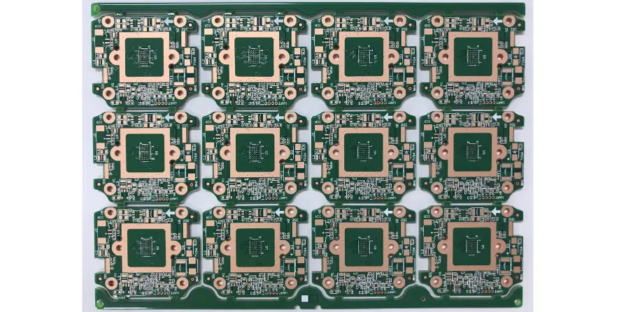
A gaming chair PCB is the electronic control platform for powered chair features such as haptic actuators, audio, RGB lighting, user controls, sensors and connectivity. The difficult part is not adding each feature separately; it is making high-current, low-noise and moving-cable domains coexist safely in furniture that users rotate, recline and touch.
Key Takeaways
- Define the product tier and system boundaries before selecting the PCB stack-up. A chair with one vibration motor and a chair with multi-zone haptics, audio and wireless control are different electrical products.
- Partition motor, LED, audio, logic and radio power paths so one feature cannot brown out, reset or contaminate another.
- Treat connectors, cables, strain relief and moving joints as part of the circuit. Many chair failures occur outside the board outline.
- Validate haptics with the actual chair structure and user load; validate RGB at worst-case brightness and cable length; validate audio while every switching load is active.
- Freeze the applicable furniture, electrical, radio, EMC, chemical and battery requirements by target market. PCB tests support compliance but do not replace complete-chair evaluation.
- Put current limits, fault behavior, cable-cycle tests, test fixtures, firmware and traceability into the RFQ rather than asking only for a board price.
Table of Contents
- What electronics are inside a gaming chair?
- How should the gaming chair PCB architecture be partitioned?
- Which haptic actuator and driver approach should be used?
- How should RGB, audio and connectivity coexist?
- How should moving cables and connectors be designed?
- What power, thermal and protection evidence is needed?
- How should the complete chair be validated?
- Common gaming chair PCB failure modes
- Gaming chair PCB RFQ checklist
- Reference standards and specifications
- Frequently asked questions
What Electronics Are Inside a Gaming Chair?
Current products show several valid feature architectures. X Rocker markets chairs that combine speakers, subwoofers, vibration motors, RGB lighting and Bluetooth. Cooler Master's Motion 1 uses D-BOX haptic technology to create movement and vibration. Razer's Project Madison concept combines multi-zone haptics, integrated audio and reactive RGB. These examples prove that “gaming chair electronics” is not one standard circuit.
Start by placing the product in a functional tier instead of assuming that premium features require a fixed layer count or HDI construction.
| Product scope | Typical electronic blocks | Dominant engineering risk | Practical board strategy |
|---|---|---|---|
| accessory lighting | LED strip, controller and external low-voltage supply | voltage drop, connector polarity and ESD | small controller or external module; avoid unnecessary integration |
| audio chair | Bluetooth or wired audio, amplifier, speakers and controls | audible switching noise, ground loops and user-accessible connectors | separate audio return and power filtering; test all source modes |
| vibration chair | audio envelope or host command, motor driver and one or more actuators | current surge, structural resonance and driver heating | protected motor rail with measured current and temperature margin |
| multi-zone haptic chair | host software, MCU, multiple drivers/actuators and diagnostics | latency, synchronization, mechanical amplification and fault containment | distributed or zoned architecture based on harness length and serviceability |
| powered ergonomic chair | actuator control, position sensing, limit handling and user controls | pinch/motion hazards, stalled motor and cable fatigue | safety-oriented state machine with current, position and timeout supervision |
| integrated premium chair | haptics, audio, RGB, radio, sensors and USB power | interaction among every domain | modular power and data boundaries with independent fault logging |
Feature selection must follow the user experience and compliance plan. A Hall sensor can measure position without mechanical contact, but it is not automatically better than a qualified switch, encoder or potentiometer. Likewise, wireless charging, biometric sensing and powered recline add thermal, privacy, radio or motion-safety responsibilities that must be justified at the product level.
How Should the Gaming Chair PCB Architecture Be Partitioned?
The most useful architecture decision is where each load receives power, where its return current flows and what happens when it faults.
| Domain | Electrical behavior | Keep separate from | Evidence needed at release |
|---|---|---|---|
| input power and protection | adapter transients, inrush, reverse-polarity or wrong-adapter exposure | MCU and audio reference | input range, polarity, current limit, surge/inrush and abnormal-input results |
| logic and control | MCU, memory, watchdog, interfaces and sensor acquisition | motor and LED switching loops | startup, brownout, watchdog, firmware version and recovery logs |
| haptic or motion drive | pulsed or bidirectional current, inductive energy and fault current | radio, audio input and high-impedance sensors | current waveform, stall/open/short response and driver temperature |
| RGB lighting | high aggregate DC current and fast serial edges | audio input and antenna region | worst-pattern current, far-end voltage and data-eye/noise margin |
| audio | low-level input plus class-D or analog amplifier output | LED data, DC/DC switch node and motor current | noise, clipping, load, mute/pop and coexistence test |
| wireless | RF transceiver, antenna and burst current | metal frame, motor cables and noisy converters | antenna keep-out, final-chair RF performance and regulatory test plan |
| user and service interfaces | buttons, USB, jacks, programming and diagnostics | unsafe energy and uncontrolled discharge paths | ESD path, connector life, misuse test and service procedure |
Use one main board only when harness reduction outweighs the routing, thermal and service penalties. A distributed system can place an LED or button board near the user interface and a driver board near the actuator, reducing high-current cable length. The trade-off is more connectors, firmware interfaces and change-controlled assemblies.
Do not prescribe two, four or six layers by marketing tier. Layer count follows routing density, reference-plane continuity, EMC risk, creepage/clearance needs, thermal spreading, board size and cost. A compact mixed-signal controller may justify a multilayer PCB; a simple protected LED board may remain a two-layer FR-4 design.
Which Haptic Actuator and Driver Approach Should Be Used?
“Haptic motor” can refer to devices with very different control needs. Small eccentric rotating mass (ERM) motors create vibration through an offset mass. Linear resonant actuators (LRAs) operate around a mechanical resonance and can provide sharper effects when driven correctly. Larger voice-coil, shaker or motion actuators transfer force into the chair structure and require a power stage and mechanical design appropriate to their impedance, travel and duty cycle.
TI's DRV2605L is an example of a low-voltage haptic driver that supports ERM and LRA actuators, waveform playback and LRA resonance tracking. It illustrates why actuator type must be frozen before driver selection. It does not represent a suitable driver for every seat-scale transducer or powered adjustment motor.
| Decision | ERM | LRA | Larger haptic or motion actuator |
|---|---|---|---|
| control variable | motor voltage/PWM and spin dynamics | drive near resonant behavior | current, voltage, position or audio/telemetry waveform according to actuator |
| useful strength | simple, low-cost vibration | faster, more defined local cues | higher force and body-coupled effects |
| main limitation | slow start/stop and moving wear parts | narrow mechanical operating region | power, heat, structure, noise and safety complexity |
| PCB implication | protected low-side or full driver as direction requires | dedicated closed-loop-capable driver may help | external power stage, current measurement, fault handling and larger connectors |
| production test | spin/current response and orientation | frequency/response calibration | force/acceleration correlation in a controlled mechanical fixture |
The chair frame, foam, mounting torque and occupant load form part of the transfer function. A waveform that feels strong on a bare actuator can disappear after installation or excite an unwanted buzz. Release criteria should therefore include electrical current and voltage, actuator diagnostics and a repeatable mechanical response measurement. A subjective “feels good” check is useful during tuning but is not a production limit.
If haptics are generated from audio, define filtering, gain, clipping and quiet-scene behavior. If effects arrive from game telemetry or host software, define update rate, buffering, loss-of-link behavior and compatibility ownership. These two modes can coexist, but they have different latency and content-support risks.
How Should RGB, Audio and Connectivity Coexist?
RGB lighting, audio and radio functions often fail only when operated together. The board must be tested with the LED pattern that draws the most current, the amplifier load that produces the largest supply modulation, active wireless traffic and simultaneous haptic drive.
For addressable RGB, calculate the real maximum from the chosen LED data sheet, channel limits, brightness cap and zone count. Do not multiply an internet “per LED” rule without considering the actual part and firmware. Measure voltage at the far end of the installed strip and through every connector. Long single-ended data paths may need a source resistor, buffer, differential transport or a local controller depending on cable length and noise.
For audio, keep the low-level input and reference away from switch nodes, LED data and motor current loops. Confirm amplifier load, output filter requirements, speaker wiring and thermal behavior from the selected device data. Test mute, startup, shutdown, Bluetooth reconnection and source switching for pops or unintended full-scale output.
For Bluetooth, Wi-Fi or another radio, preserve the antenna manufacturer's keep-out and tune in the finished chair. Steel frames, fasteners, seat mechanisms, occupant proximity and moving cables can alter RF performance. A pre-certified module can reduce radio design work, but it does not eliminate final-host integration, EMC, labeling or market approval responsibilities.
USB charging or USB-C adds a user-accessible power interface, not just a connector. Specify advertised current or power, role, cable behavior, overcurrent response, thermal limit and whether USB Power Delivery is actually implemented. A USB-C receptacle without the required configuration and protection is not a complete charging solution.
How Should Moving Cables and Connectors Be Designed?
The highest-value reliability asset for this product is a movement-zone map. It connects each chair motion to a cable route, conductor stress, electrical consequence and verification method.
| Movement zone | Likely stress | Electrical consequence | Design control | Validation evidence |
|---|---|---|---|---|
| swivel base | repeated torsion or winding | intermittent power/data, short or pulled connector | rotation limit, slip-ring strategy or routed service loop | full-angle cycle with powered logging |
| recline hinge | bending, pinch and abrasion | open conductor, insulation damage or noisy sensor | defined neutral axis, abrasion sleeve and mechanical stop | cycle at temperature with post-test resistance/inspection |
| adjustable armrest | short-radius multidirectional motion | button/LED failure or connector pullout | local daughterboard, strain relief and qualified flex path | worst-path cycling plus pull/retention test |
| seat/back interface | compression and user load | cracked wire or fretting contact | protected channel, locking connector and slack control | loaded-chair cycle and vibration test |
| haptic actuator lead | continuous vibration | terminal fretting, solder fatigue or radiated noise | crimped harness, connector retention and controlled return pair | energized vibration endurance and contact-drop monitoring |
| external adapter lead | snag, roll-over and wrong-adapter use | power interruption, exposed damage or overvoltage | keyed input, anchoring, bend relief and input protection | flex, pull, misuse and abnormal-input test |
A flex PCB can help in a controlled bend zone, but it is not a universal replacement for a cable harness. Define whether the motion is static, installation flex or repeated dynamic flex; then specify copper construction, bend radius, stiffener transitions, neutral-axis placement and cycle count. Avoid solder joints at the highest-strain point.
For wire harnesses, drawings should control wire size, insulation, twist, shield termination, crimp, connector keying, retention, labels and routing. IPC/WHMA-A-620 provides acceptance criteria for cable and wire harness assemblies, while the product drawing must still define the application-specific motion and electrical requirements.
What Power, Thermal and Protection Evidence Is Needed?
Build the power budget by operating state, not by summing only typical currents. Include adapter tolerance, startup, amplifier peaks, motor acceleration or stall, full-brightness lighting, radio transmission, USB load and converter efficiency. Then define which combinations firmware permits.
| Evidence | What to record | Decision it supports |
|---|---|---|
| state-based current table | average, peak, duration and repetition for each feature combination | adapter rating, connector/wire size and fuse/current limit |
| rail transient capture | minimum/maximum voltage at MCU, driver, LEDs and audio rail | capacitance, converter response and brownout margin |
| protection test | reverse polarity, wrong approved-class adapter, shorted output and hot plug | input topology and recoverable/nonrecoverable fault policy |
| temperature map | ambient, enclosure state, foam/frame proximity and stabilized component temperatures | copper, via, package and firmware derating decisions |
| fault injection | open/short actuator, stalled motion, disconnected sensor and stuck button | safe state, diagnostic coverage and service response |
Use IPC-2152 as a starting reference for current-carrying conductor design, then validate temperature rise on the actual board and enclosure. “Thicker copper” is not a substitute for checking connector pins, vias, pours, thermal bottlenecks and duty cycle. High-Tg laminate does not make an overheating design safe; select high-Tg PCB material only when the thermal, assembly or reliability profile justifies it.
User-accessible controls and connectors need a deliberate ESD path to chassis or circuit reference without routing discharge through the MCU reset, audio input or radio. Inductive loads need appropriate recirculation or clamp paths. The selected driver may provide overcurrent or thermal flags, but firmware must define how faults are latched, retried, reported and cleared.
How Should the Complete Chair Be Validated?
PCB bring-up is only the first level. The release plan must prove the assembled chair across electrical load, motion, environment, software and misuse.
- Board-level bring-up: verify rails, clocks, programming, interfaces, protection thresholds and each load independently.
- Subsystem correlation: characterize the actuator in its mounting, the LED strip through its final harness, audio with its speaker enclosure and radio in its antenna location.
- Feature coexistence: run worst-case haptic, RGB, audio, radio and USB states while logging rail, reset, communication and thermal data.
- Mechanical endurance: cycle swivel, recline, armrests and controls under defined load while monitoring continuity and event logs.
- Immunity and emissions: test ESD and other applicable disturbances on the final chair; perform pre-compliance emissions scans in representative operating modes.
- Abnormal operation: inject short, open, stall, blocked ventilation, wrong sequence and communication loss within the approved safety plan.
- Production correlation: convert engineering measurements into fixtures and limits that distinguish a good unit from a marginal one.
UL 962 covers electrified and motor-operated household and commercial furnishings within its scope in the U.S. ANSI/BIFMA X5.1 addresses general-purpose office-chair safety and performance, but whether it applies to a specific gaming chair depends on product classification and market claims. Wireless products may also invoke radio rules, and integrated audio/ICT functions can bring additional equipment standards. Confirm the complete standard set with the responsible compliance laboratory before layout freeze.
Common Gaming Chair PCB Failure Modes
| Symptom | Likely causes | Best discrimination check |
|---|---|---|
| chair resets when haptics start | adapter droop, shared impedance, converter limit or poor brownout handling | capture input, MCU rail, reset and motor current on one timebase |
| RGB flickers at high brightness | far-end voltage drop, data reflection, ground offset or connector resistance | measure strip input/far-end voltage and data waveform in final harness |
| buzz appears in speakers | shared return path, DC/DC beat, class-D coupling or motor PWM | mute domains separately and probe supply/audio reference spectra |
| intermittent control after recline cycles | conductor fatigue, pinch, crimp or connector fretting | powered continuity log through the full motion path |
| one haptic zone feels different | actuator variation, mounting/foam difference, driver calibration or structural resonance | swap electrical channels, then compare current and mechanical response |
| wireless range changes with chair position | frame/occupant detuning, cable movement or switching-noise coupling | measure final-product RF behavior at defined positions and feature states |
| driver overheats only with an occupant | changed mechanical load, stall-like current or blocked heat path | correlate current and case/board temperature under controlled load |
| repeated field damage from adapters | ambiguous connector, missing reverse/overvoltage protection or unsupported supply | abnormal-input test and returned-unit power-path inspection |
Gaming Chair PCB RFQ Checklist
Product and responsibility definition
- product tier, target markets, intended users and complete feature list;
- mechanical chair classification, electrical/furniture compliance plan and responsible test laboratory;
- radio, battery, USB charging, audio and powered-motion scope;
- firmware, host application, haptic content and security/update ownership.
Electrical and PCB package
- schematic, BOM with approved alternatives, Gerber/ODB++ or IPC-2581, drill, stack-up and fabrication notes;
- input adapter range, power-state table, rail limits, load waveforms and protection requirements;
- actuator, speaker, LED, sensor, radio-module and connector exact part numbers;
- controlled impedance, current, creepage/clearance, copper, finish and thermal requirements where applicable.
Mechanical and harness package
- 3D board/enclosure data, mounting hardware, keep-outs, foam/frame proximity and airflow assumptions;
- swivel, recline, armrest and user-load motion envelopes;
- harness drawings with wire, crimp, connector, shield, label, routing and retention requirements;
- flex bend type/radius/cycles, strain relief, pinch/abrasion protection and service access.
Test and production package
- programming files, firmware checksum, calibration and secure provisioning requirements;
- ICT/flying-probe coverage, SPI, AOI, X-ray where package geometry requires it and functional fixtures;
- load simulators or real actuators/speakers/LEDs, pass/fail thresholds and raw-data retention;
- movement-cycle, ESD, EMC pre-compliance, thermal, abnormal-input and fault-injection plan;
- serialization, PCB/BOM/firmware/harness traceability, retained samples and change-notification rules.
HILPCB can review the fabrication and assembly package, partitioning, high-current paths, connector footprints, test access and panelization before quoting prototype assembly, SMT assembly or a turnkey PCB assembly scope. Complete-chair safety, mechanical performance, radio approval, haptic tuning and market compliance remain with the designated product owner unless explicitly included in an approved test plan.
Reference Standards and Specifications
- UL 962 — UL Standards & Engagement
- ANSI/BIFMA X5.1 — Business and Institutional Furniture Manufacturers Association
- IEC 62368-1 — International Electrotechnical Commission
- IEC 61000-4-2 — International Electrotechnical Commission
- IEC 61000-4-4 — International Electrotechnical Commission
- IEC 61000-4-5 — International Electrotechnical Commission
- IEC 60068-2-6 — International Electrotechnical Commission
- IEC 60068-2-27 — International Electrotechnical Commission
- FCC 47 CFR Part 15 — Federal Communications Commission
- ETSI EN 300 328 — European Telecommunications Standards Institute
- IPC-2221 — IPC
- IPC-2152 — IPC
- IPC-A-610 — IPC
- IPC/WHMA-A-620 — IPC and Wire Harness Manufacturers Association
- USB Type-C and USB Power Delivery Specifications — USB Implementers Forum
Apply only the standards, revisions and regional requirements confirmed for the released product and its intended markets.
Frequently Asked Questions
Does every premium gaming chair need a six-layer HDI PCB?
No. Layer count and HDI features follow component density, routing, reference planes, EMC, thermal and mechanical constraints. A modular premium chair may use several simpler boards, while a compact integrated controller may need more layers.
Which is better for a gaming chair, an ERM or an LRA?
Neither is universally better. ERMs are simple and economical; LRAs can provide faster localized effects around their operating resonance. Seat-scale force may require a larger transducer or motion actuator. Select by required sensation, structure, power and control method.
Can haptic feedback be driven directly from game audio?
Yes, an audio-derived mode can work across many sources, but filtering and gain determine whether effects are useful or merely continuous rumble. Telemetry-driven effects can be more specific but require supported software and defined loss-of-link behavior.
Should moving chair connections use flex PCB or wire harnesses?
Use the interconnect qualified for the motion. A harness is often easier to route and service; a flex circuit can suit a controlled compact bend. Both require defined bend radius, strain relief, cycle count, connector retention and abrasion protection.
Is a pre-certified Bluetooth module enough for compliance?
No. It can reduce radio design and testing work, but the final chair still needs correct antenna integration, host EMC evaluation, labeling, software configuration and the approvals required in each target market.
What should a gaming chair PCB functional test verify?
Verify rails, current, firmware, controls, sensors, communications, every load output and relevant diagnostics. Correlate representative actuators, LEDs and audio loads with fixtures, then retain serial-number-linked results and calibration status.
What files are needed for a gaming chair PCB quote?
Provide fabrication and assembly data, BOM, mechanical constraints, feature and power states, actuator/LED/audio specifications, harness drawings, firmware, compliance scope, test limits, quantities and traceability requirements.
Build the Chair as One Verified Electromechanical System
A reliable gaming chair controller is defined by boundaries and evidence: each load has a controlled power path, each moving interconnect has a qualified motion envelope, each fault reaches a known safe state and each production test correlates to a real product requirement. Freeze those decisions before requesting price, then validate the PCB, harness, firmware and chair structure as one system.