
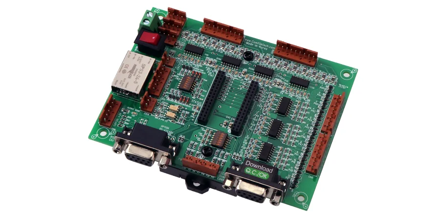
In Industry 4.0 and smart manufacturing, the human-machine interface is where operators meet the machine — and the board behind it decides whether that interaction stays reliable. A Human Machine Interface (HMI) PCB is not just a display driver; it carries control commands, real-time data, and the burden of surviving a factory floor. Get it wrong and you get data errors, command latency, or downtime that costs far more than the board ever did.
This guide is for hardware engineers and sourcing teams specifying industrial HMI, graphic terminal, and industrial-tablet electronics. It covers the four decisions that separate a rugged HMI board from a repurposed consumer one: environmental design, power and signal integrity, materials and process, and assembly with proper validation.
Industrial HMI PCBs are different because their released mission profile may include wide temperature cycling, continuous vibration, conductive dust, corrosive contamination, electrical transients, and long service-life requirements. Those conditions must be converted into component, layout, enclosure, process, and test requirements rather than assumed from an "industrial-grade" label.
Key Takeaways
- Define temperature, vibration, contamination, duty cycle, display interface, and service life before selecting the stack-up or components.
- Protect field power and communication ports against the transients and EMC environment specified for the installation.
- Treat the display link, touch controller, processor, backlight power, and industrial network interfaces as separate noise and test domains.
- Match coating, cleanliness, connector retention, and test coverage to the actual enclosure and contamination risk.
- Put inspection, programming, functional-test limits, traceability, and change-control requirements in the RFQ.
Why Industrial HMI PCBs Face Harsher Requirements Than Consumer Boards
Consumer electronics live in climate-controlled comfort. Industrial HMI devices sit on factory floors, in outdoor cabinets, and on moving equipment — and that changes the entire design brief.
- Wide temperature range. Deployments span −40 °C cold storage to +85 °C process areas. Materials, components, and solder joints have to take the full cycle without drift or cracking.
- Vibration and shock. Motors, presses, and vehicles crack solder joints and shake components loose. The layout has to fight back with mechanical support and smart component placement.
- Dust and moisture. Metal dust, oil mist, and humidity can corrode conductors or create leakage paths. Conformal coating may help, but only after material compatibility, cleanliness, coverage, masking, repair, and enclosure ingress protection are defined.
- Electromagnetic compatibility (EMC). Drives, VFDs, and switching gear flood the plant with EMI. An HMI board needs real immunity or it misreads inputs and mis-fires outputs.
- Chemical corrosion. In plating and chemical plants, corrosive gases attack copper and pads, which pushes surface finishes toward corrosion-resistant options like ENIG.
The takeaway is simple: dropping a commercial-grade design into an industrial enclosure is a failure waiting for a duty cycle. Every one of these stresses has to be designed for from the start.
Key Design Considerations for Reliable HMI PCBs
A dependable HMI board balances reliability, performance, and cost at the schematic and layout stage — not after the first field return.
Component Selection and Layout
Industrial-grade parts are the foundation: wider temperature range, longer life, and better vibration tolerance than commercial equivalents. In turnkey assembly, that also means a supply chain vetted for long-term availability, because a 10-year product can't be built around a part that goes end-of-life in three. For layout, isolate sensitive analog from high-frequency digital, place heavy parts (connectors, inductors) over mechanical support, and keep them away from board edges where vibration stress concentrates.
Power Integrity (PI)
A stable rail is the lifeline of an industrial computer board. Priorities:
- Low-impedance power delivery — full power and ground planes with wide traces for high-current paths to minimize voltage drop.
- Adequate decoupling — capacitors sized and placed at each IC's power pins to filter noise and supply instantaneous current.
- Power-domain isolation — separate analog, digital, and interface supplies so noise doesn't cross-couple.
Thermal Management
Processors and LED backlights are the main heat sources; excess temperature shortens component life or triggers shutdown. Effective strategies:
- Thermal via arrays under hot components to move heat to a back-side plane or heatsink.
- Large copper pours tied to component ground pins, using copper's conductivity to spread heat.
- High-conductivity substrates — for high-power designs, a High-Tg PCB with a higher glass-transition temperature holds up better under sustained heat.
| Design input | Evidence to define | Why it matters |
|---|---|---|
| Operating temperature | Released ambient, internal hot spots, ramp rate, dwell, cycle count, and powered/unpowered states | Component grade alone does not prove board-level operation |
| Vibration and shock | Mounting method, axis, spectrum or pulse, duration, fixture, and acceptance checks | Connector and heavy-component stress depends on the installation |
| EMC and transients | Applicable IEC 61000-4 test methods, levels, coupling paths, operating modes, and pass/fail behavior | A standard family name without levels is not a test plan |
| Lifecycle support | Approved alternates, obsolescence monitoring, change notification, firmware compatibility, and service stock | Long-life availability is a program control, not a laminate property |
Materials & Manufacturing for Rugged Industrial Tablet PCBs
Industrial tablets get moved, dropped, and knocked — so physical robustness starts in the material and process choices, not just the enclosure.
Substrate. Standard FR-4 is cost-effective but can fall short on thermal and mechanical margin. High-Tg FR-4 (Tg above ~170 °C) has a lower Z-axis expansion coefficient at temperature, which improves via reliability and reduces thermal-stress failures.
Copper weight. For boards driving motors or multiple peripherals, power paths may carry significant current. Heavy copper PCB construction (3 oz and above) lowers trace impedance and temperature rise, improving efficiency and stability.
Surface finish. HASL's uneven surface is poor for fine-pitch assembly. ENIG (Electroless Nickel Immersion Gold) gives a flat, oxidation- and corrosion-resistant surface that suits high-density, high-reliability industrial boards. Matching finish to application and cost target is part of the design conversation, not an afterthought.
Signal Integrity for High-Resolution HMI Displays
Modern HMIs use high-resolution touchscreens, and their display interfaces — LVDS, MIPI DSI, eDP — run at gigabit rates. At those speeds, small layout flaws become visible defects: flicker, artifacts, dropped frames. Sound high-speed PCB practice keeps them clean:
- Impedance control. Match trace impedance to driver and receiver to avoid reflections; verify with TDR in production, typically to a ±5% tolerance.
- Differential length matching. Match intra-pair (P/N) and inter-pair (clock/data) lengths to control skew, and hold consistent spacing to keep differential impedance stable.
- Optimized vias. Vias are discontinuities; tune pad/anti-pad geometry and add adjacent ground vias at layer transitions to limit reflections.
- Continuous reference plane. Keep an unbroken ground or power plane under every high-speed trace so return current takes the shortest path — the single biggest lever on crosstalk and radiation.
Industrial HMIs are also communication hubs, and the bus you support shapes the layout:
| Protocol | Physical layer | Key PCB considerations | Typical use |
|---|---|---|---|
| Modbus RTU | RS-485 / RS-232 | Differential routing (RS-485), termination matching, ESD protection | Cost-sensitive master-slave networks |
| PROFINET / EtherNet/IP | Ethernet (100/1000 Mbps) | 100 Ω differential control, magnetics layout, RJ45 EMC | Real-time lines integrated with IT |
| EtherCAT | Ethernet (100 Mbps) | Strict clock sync; careful PHY clock routing | High-precision motion control |
| CANopen | CAN bus | 120 Ω differential control, bus topology, termination | Vehicles, machinery, distributed control |
From PCB to Finished Product: Industrial PCBA Assembly & Testing
A clean bare board is half the job; on an industrial computer board, assembly process control decides the rest.
- Industrial-grade handling. Specialized equipment for high-temperature BGAs and vibration-proof connectors, with controlled reflow profiles for long-term joint reliability.
- Conformal coating. Automated coating insulates and protects circuits against humidity, dust, and corrosive gases — the practical realization of a dustproof design.
- Rigorous test. Beyond continuity: AOI for solder defects, plus ICT or functional test (FCT) to confirm the assembly meets spec.
- Environmental stress screening (ESS). Thermal cycling and vibration flush out early-life failures before shipment on high-reliability products.
Running DFM analysis, procurement, fabrication, SMT/THT assembly, and test as one workflow shortens time-to-market and simplifies supply-chain management — one accountable partner instead of a chain of hand-offs.
What Should an Industrial HMI PCB RFQ Include?
Send the released files and the operating evidence needed to quote the same product your engineering team intends to validate:
- Schematics, fabrication and assembly data, BOM with approved alternates, stack-up, impedance table, mechanical drawings, and revision history
- Display, touch, memory, Ethernet, fieldbus, isolated-I/O, backlight, audio, and power-interface requirements
- Input-voltage range, surge and ESD levels, grounding and shielding scheme, EMC operating modes, and cable definitions
- Temperature, humidity, contamination, vibration, ingress, coating, cleanliness, flammability, and service-life requirements
- Programming files, test points, fixtures, loads, pass/fail limits, calibration needs, sample plans, and retained test records
- Prototype and production quantities, panel constraints, serialization, packaging, approved substitutions, and change-notification rules
Reference Standards and Responsibility Scope
Confirm the current revision and exact applicability for the end product and target market.
- IPC-2221 — IPC
- IPC-6012 — IPC
- IPC-A-600 — IPC
- IPC-A-610 — IPC
- IPC J-STD-001 — IPC
- IEC 61000-4 series — International Electrotechnical Commission
- IEC 60529 — International Electrotechnical Commission
HILPCB can fabricate and assemble the released PCB, apply agreed process controls, and provide contracted inspection and test records. The product owner retains responsibility for system architecture, functional safety, EMC and environmental qualification, enclosure ingress performance, software, cybersecurity, and final regulatory approval unless those tasks are explicitly included in a validated scope.
Frequently Asked Questions
Why can't an industrial HMI PCB be treated like a consumer board?
An HMI board runs in electrically noisy, vibration-prone, long-life environments. That forces EMC immunity, power stability, connector strength, and maintainability to the front — ahead of the compactness and low unit cost that drive consumer design.
What reliability priorities matter most for industrial HMI design?
Material stability, surge and EMI protection, reinforced interfaces, and controlled thermal behavior. A strong platform balances display driving, touch, communications, and power integrity without becoming fragile in the field.
Why plan manufacturing, assembly, and validation together?
Industrial HMI failures often come from process interaction, not just schematic errors. Aligning fabrication, assembly controls, and validation for temperature, vibration, and EMC early makes the product far more predictable in production and in service.
What surface finish is best for industrial HMI PCBs?
ENIG is a common choice: flat enough for fine-pitch assembly and resistant to oxidation and corrosion. The final call weighs application environment against cost.
Conclusion
An industrial HMI board is only as good as its weakest environmental margin. Reliability comes from designing for the full stress envelope — temperature, vibration, dust, EMC, and a decade of supply — then backing it with the right materials, controlled fabrication, and validated assembly. Skipping any layer just moves the failure downstream, where it costs more.
HILPCB builds high-reliability industrial PCBs and PCBAs end to end, from DFM and material selection through SMT/THT assembly, conformal coating, and environmental screening. If you're specifying an HMI, industrial-tablet, or graphic-terminal board, send us your requirements and our engineers will help align the design, materials, and process before the first build.