
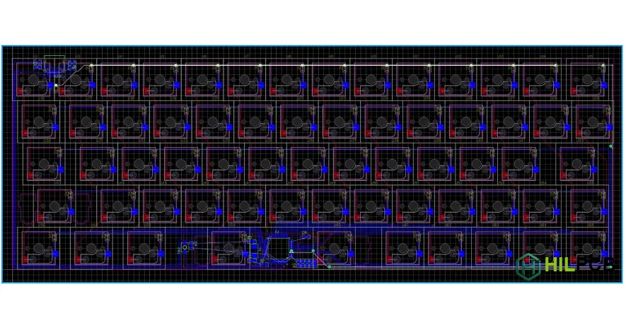
Custom mechanical keyboards rely on well-designed PCBs that determine switch compatibility, layout flexibility, and firmware features. This guide covers the complete design process from architecture decisions through manufacturing, with practical recommendations for cost-effective and reliable keyboard builds.
HILPCB supports keyboard projects from single prototypes to group buy production runs, with manufacturing capabilities suited for both standard keyboard designs and advanced high-density applications.
In This Guide
- PCB Architecture Options
- Microcontroller Selection
- Switch Footprint Design
- Matrix Circuit and Diodes
- USB Interface Design
- RGB Lighting Implementation
- Design Rules and Manufacturing
PCB Architecture Options
The fundamental architecture decision affects durability, cost, manufacturing complexity, and USB port positioning flexibility. Understanding the trade-offs helps you choose the right approach for your specific project goals and budget.
Single-PCB designs mount the USB connector directly on the main switch board. This approach reduces component count, simplifies assembly, and lowers cost—making it ideal for budget keyboards, prototypes, and designs where simplicity is prioritized. The trade-off is that cable insertion and removal stress transmits directly to the main PCB, potentially affecting long-term reliability with heavy use.
Daughterboard designs separate the USB connector onto a small auxiliary PCB, connected to the main board via JST-SH cable or FFC ribbon. This isolation protects the main switch matrix from mechanical stress, enables flexible USB port positioning (bottom-mount, side-mount, or centered), and allows main PCB redesigns without changing the USB interface. Premium custom keyboards typically use this approach despite the added cost and complexity.
Form Factor Standards
Standard form factors have established dimensions ensuring compatibility with cases, plates, and keycaps:
- Full-size (104-108 keys): ~440×140mm, includes numpad and function row
- TKL/Tenkeyless (87-88 keys): ~360×140mm, removes numpad
- 75% (82-84 keys): ~330×140mm, compact arrangement with function row
- 65% (66-68 keys): ~315×105mm, removes function row, keeps arrows
- 60% (61-64 keys): ~285×95mm, most popular custom format
- 40% (40-48 keys): ~230×80mm, heavily layer-dependent
The 60% format dominates the custom keyboard community due to its large ecosystem of compatible components. The universal 19.05mm (0.75") key spacing standard ensures cross-compatibility regardless of manufacturer.
Component placement strategies are detailed in keyboard PCB layout.
Microcontroller Selection
The microcontroller determines firmware compatibility, feature capability, available I/O pins, and cost. Your choice affects not just what the keyboard can do, but also community support, documentation availability, and ease of development.
ATmega32U4 remains the classic choice, offering native USB HID support without external interface chips, 26 GPIO pins sufficient for most layouts, and comprehensive QMK/VIA support with years of community documentation. The primary limitations are 32KB flash (constrains complex RGB animations and extensive macros) and increasingly difficult component availability during shortages.
STM32F072/F103 brings 32-bit ARM Cortex-M architecture with more I/O pins, significantly more flash/RAM for advanced features, and faster processing. The F072 includes native USB; the F103 requires an external crystal for USB timing. QMK support has matured considerably, making these excellent choices for feature-rich designs.
RP2040 has emerged as an excellent modern option with dual-core ARM Cortex-M0+, 30 GPIO pins, programmable I/O (PIO) blocks ideal for driving addressable LEDs without CPU overhead, excellent availability, and competitive pricing. Strong QMK support makes it increasingly popular for new designs.
Essential Support Circuits
Regardless of MCU choice, reliable operation requires proper support circuitry:
- Crystal/Resonator: 16MHz for ATmega32U4, 8MHz for STM32F072—required for accurate USB timing
- Decoupling Capacitors: 100nF ceramic on each VCC pin plus 10μF bulk capacitor near power input—place as close to MCU pins as physically possible
- Reset Circuit: 10kΩ pull-up resistor with optional tactile button for bootloader entry during development
- Programming Header: ISP for ATmega, SWD for STM32/RP2040—enables firmware recovery if USB bootloader fails
- Voltage Regulation: 3.3V LDO if MCU requires lower voltage than 5V USB supply
Switch Footprint Design
Switch footprints must accommodate mechanical switches while providing electrical connections and supporting optional features like hot-swap sockets and LEDs. Cherry MX-compatible footprints have become the universal standard, supported by switches from Cherry, Gateron, Kailh, Durock, JWK, and dozens of other manufacturers.
The standard MX footprint includes a 4.0mm center hole for switch housing alignment and two 1.27mm metal pin holes at 6.35mm horizontal spacing. These dimensions are non-negotiable—even small deviations prevent switch insertion or cause binding during actuation.
Five-pin (PCB-mount) switches add two plastic alignment pins requiring 1.7mm holes. Including these enables plateless builds where the PCB alone supports the switches—useful for certain case designs and reducing build complexity.
Hot-swap sockets have become essential for enthusiast keyboards. Kailh sockets mount on the PCB bottom via 2.55mm square pads at 6.35mm spacing, sitting 1.8mm below the PCB—verify case clearance before committing to hot-swap design. Mill-Max sockets (0305/7305 series) install into through-holes, enabling hot-swap capability with standard footprints.
Universal footprints combining all options (MX pins, PCB-mount pins, hot-swap pads, LED positions, diode pads) allow one PCB design to support multiple build configurations—maximizing flexibility for group buy projects.
Detailed specifications in keyboard PCB layout.
Keyboard Matrix Quick Reference
Matrix Circuit and Diodes
Matrix circuits dramatically reduce I/O requirements—a 61-key keyboard uses an 8×8 matrix requiring only 16 MCU pins instead of 61 (74% reduction). The MCU scans by driving rows LOW sequentially while reading columns; pressed switches pull their column LOW, indicating a keypress at that intersection.
Ghosting occurs when three keys forming a rectangle are pressed simultaneously—current flows through unintended paths, falsely detecting a fourth key. This fundamental limitation would restrict keyboards to detecting only certain key combinations without mitigation.
Per-switch diodes solve ghosting by allowing current to flow in only one direction. With diodes correctly installed, the keyboard achieves N-key rollover (NKRO)—any combination of keys detected accurately. This is why all quality mechanical keyboards include one diode per switch.
Two standard configurations exist: COL2ROW (cathode toward row, QMK default) and ROW2COL (cathode toward column). Both work equally well—choose based on routing convenience, but ensure firmware configuration matches hardware exactly.
Common diode options: 1N4148 through-hole for hand-soldering, 1N4148W (SOD-123) for standard SMT, 1N4148WS (SOD-323) for compact layouts, BAV70 dual-diode (SOT-23) to serve two switches per package.
Comprehensive theory in keyboard matrix design. Orientation details in keyboard diode direction.
USB Interface Design
USB Type-C has become the standard connector for modern keyboards, offering reversible connection, robust mechanical design, and broad device compatibility. Proper implementation ensures reliable enumeration across different host systems.
USB 2.0 Full Speed (12 Mbps) provides far more bandwidth than keyboards require. The critical design aspects are signal integrity: route D+/D- as a differential pair targeting 90Ω impedance, length-matched within ±2mm, keeping total length under ~100mm. Series resistors (22Ω) near the MCU provide impedance matching.
USB Type-C specifics: Each CC pin requires a 5.1kΩ pull-down resistor to signal device mode. Add VBUS decoupling capacitor near the connector. Connect shield to ground through 1MΩ resistor for ESD path without ground loops.
ESD protection is essential—keyboards face significant electrostatic exposure during normal use. Place TVS diode arrays (USBLC6-2, TPD2EUSB30, or similar) as close as possible to the USB connector to clamp voltage transients before they reach the MCU.
RGB Power Considerations (60-Key Example)
RGB Lighting Implementation
Per-key RGB lighting has become an expected feature, but introduces significant design complexity—particularly around power management. Understanding the constraints prevents frustrating debugging later.
WS2812B and SK6812 LEDs integrate controller and RGB elements, requiring only a single data line regardless of LED count. Each LED can draw up to 60mA at full white brightness, though typical varied-color operation averages 15-20mA. A 60-key board at full white could theoretically draw 3.6A—over 7× the USB 2.0 500mA limit.
Practical solutions: Most keyboards implement firmware brightness limiting (30-50% maximum) to stay within USB power. Some designs include USB Power Delivery negotiation for higher current, or provide separate 5V power input for full brightness capability.
LED placement: South-facing (below switch center) ensures compatibility with all keycap profiles including Cherry. North-facing provides better legend illumination but may interfere with Cherry-profile keycaps on certain switch/keycap combinations.
Power trace sizing for 1oz copper: Signal traces (100mA) need ~0.2mm width; 500mA power needs ~0.5mm; 1A RGB trunks need ~1.0mm. Use star topology from USB input to minimize voltage drop.
Trace calculations in keyboard PCB trace routing.
Design Rules and Manufacturing
Successful keyboard PCB manufacturing requires design rules matching both your design needs and manufacturer capabilities. Understanding the relationship between design choices and cost helps optimize your project.
Recommended Design Rules for Keyboards
Keyboard PCBs are relatively simple compared to high-speed digital designs. Conservative design rules reduce cost and improve yield:
- Trace/Space: 6/6mil (0.15mm) is comfortable for most keyboards and widely supported at standard pricing. 8/8mil (0.2mm) provides extra margin. Going below 5/5mil rarely benefits keyboard designs and increases manufacturing cost.
- Via Drill: 0.3mm is standard and cost-effective. Smaller vias (0.2mm, 0.15mm) are available but unnecessary for typical keyboard routing.
- Via Pad: 0.6mm minimum for 0.3mm drill provides adequate annular ring.
- Copper-to-Edge: 0.3mm clearance prevents copper exposure during board routing.
Standard Keyboard PCB Specifications
Most keyboards use these cost-effective standard parameters:
- Layers: 2-layer (sufficient for nearly all keyboard designs)
- Thickness: 1.6mm (standard, compatible with most cases)
- Copper Weight: 1oz standard; 2oz beneficial for RGB-heavy designs
- Surface Finish: HASL (economical) or ENIG (flat pads ideal for hot-swap, professional appearance)
- Solder Mask: Various colors available; black popular for premium appearance
HILPCB Manufacturing Capabilities
HILPCB offers capabilities exceeding typical keyboard requirements, supporting both standard designs and advanced applications:
- Minimum Trace/Space: 2/2mil (50μm)—available for high-density designs requiring fine features, though standard keyboards should use 6/6mil or larger for cost efficiency
- Standard Trace/Space: 3/3mil (75μm) at standard pricing
- Via Drill: 0.15mm laser minimum, 0.3mm mechanical standard
- Layer Count: 2-64 layers with ±15-25μm registration accuracy
- Impedance Control: ±5% with TDR verification for USB and other controlled-impedance traces
- Quick-Turn: 24-48 hours for standard 2-layer builds
Complete file generation in keyboard PCB Gerber files.
Why Choose HILPCB for Keyboard Projects
HILPCB supports keyboard designers from initial prototypes through volume production:
Prototype Services: Quick-turn fabrication enables rapid design iteration. Multiple solder mask colors for aesthetic matching. Small batch assembly handles MCU, diodes, hot-swap sockets, and all SMT components. Pre-production DFM review catches issues before manufacturing.
Production Services: Volume manufacturing maintains consistent quality across group buy quantities. SMT assembly from basic diode population to complete turnkey assembly with tested, programmed boards.
Submit your keyboard design for manufacturing review and quotation—our team provides feedback specific to keyboard applications.