
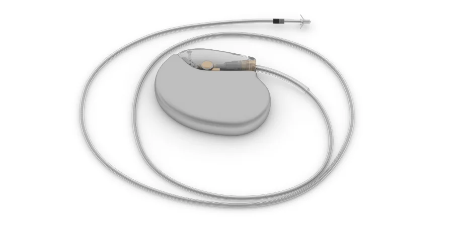
A pacemaker’s circuit assembly must fit the device’s energy budget, sensing and timing requirements, package interfaces and reliability plan. Those requirements become practical manufacturing inputs: an approved material set, controlled geometry, joining and cleaning processes, and acceptance records tied to the released configuration.
HILPCB’s published services include flex and ceramic fabrication, SMT assembly, sourcing and defined inspection/test records. These routes provide a starting point for a feasibility review. Implantable-device eligibility, any required ISO 13485 site scope, specialist die/wire-bond or hermetic work and the finished device’s qualification must be established for the specific program; general PCB capability is not that qualification.
Pacemaker PCB Design Requirements and Specifications
Implantable pulse-generator assemblies have exceptionally strict power, packaging, material and fault-tolerance constraints. Allocate them from the device design and risk controls before selecting board technology or freezing the manufacturing route.
Critical Design Parameters:
- Energy budget: Separate sensing, timing, output, telemetry and standby modes. Include regulator/quiescent current, leakage, test configuration and battery assumptions, then specify the board-level current measurements required for acceptance.
- Package fit: Release board dimensions, component heights, attachment points and lead/feedthrough interfaces with tolerances. Coordinate inspection and rework access before the assembly is enclosed.
- Sensing and timing: Define the measurement node, load/fixture, operating mode, clock reference and numerical limits for the released design. Keep low-level sensing paths and their returns clear of noisy digital or telemetry current loops.
- Diagnostic behavior: Identify the hardware controls and tests allocated by the device risk analysis. Preserve their power, reset, clock and interface requirements and specify the evidence that verifies the configured assembly.
For low-leakage circuitry, solder mask, exposed surfaces, flux residues and handling can matter alongside schematic component ratings. Identify critical nodes and cleaning restrictions on the assembly drawing so fabrication, assembly and electrical acceptance address the same features.
Biocompatible Materials for Medical PCB Manufacturing
Start with a contact and package map: which materials can contact tissue or fluid, and which remain inside the specified enclosure? FDA’s biocompatibility guidance evaluates the finished device, including relevant processing and residues. Use that assessment to define the approved material and process set rather than treating a laminate trade name as biological approval.
Advanced Substrate Technologies:
- Flex construction: HILPCB’s flex route lists PI as standard, with reviewed LCP/RA-copper options, 1–4 standard layers and advanced builds up to 8. Choose the exact dielectric, copper, adhesive/coverlay and transition geometry for the interconnect; flex fabrication capability is separate from lead or tissue-contact qualification.
- Ceramic construction: The ceramic route includes alumina and reviewed AlN/LTCC options, with metallization and finish selected for the joining process. Specify outgassing, adhesion, cleanliness and package compatibility where relevant; ceramic is not automatically a zero-outgassing assembly.
- High-Tg FR-4: Consider a released high-Tg construction only where its thermal, moisture and package requirements fit. Tg is not a continuous-use or hermetic-sealing compatibility rating.
- ENEPIG or other finish: Select the finish, thickness and surface condition for the actual soldering or wire-bond process. A wire-bondable finish does not establish a completed bond’s strength or a sealed package’s corrosion performance.
Freeze the approved grade, supplier, material revision, finish and permitted processing changes. Link substitution decisions to the package and validation evidence so a new adhesive, cleaning agent or finish does not enter a repeat build unnoticed.
EMI Shielding and Signal Integrity for Cardiac Devices
EMC review includes internal switching noise and the external electromagnetic environment. The board, leads/feedthroughs, telemetry antenna and enclosure form the relevant coupling paths. Specify their installed configuration and operating modes for the assessment.
Comprehensive EMI Mitigation Strategies:
- References and shielding: Use placement, continuous return paths and any enclosure/shield connections defined by the device architecture. Isolating circuits by a blind ground split can introduce unwanted return impedance.
- Telemetry interconnects: Define the selected radio’s channel and antenna requirements. Our impedance calculator can support an initial line estimate; fabrication uses the approved construction and measurement method.
- Sensitive signal routing: Follow the selected input topology. Differential routing, guarding and filtering are options for particular circuits, with parasitic capacitance, leakage and stability evaluated rather than applied to every net.
- Filtering and decoupling: Place and verify the specified components with the actual package/lead return paths. Include component tolerance, mounting parasitics and any effect on the measured signal.
ISO 14117 provides EMC test methodologies for the implantable cardiac devices within its scope. The device team selects the applicable configuration, methods and limits; a board coupon or generic IEC 60601 test does not replace that plan.
Supplier Quality Controls and Manufacturing Qualification for Implantable Devices
HILPCB offers implantable-PCB design and layout engineering, and can support material validation and traceability, authenticated component sourcing, calibrated test and qualification coordination, and sample-to-volume manufacturing. For eligible specialist builds, cleanroom ISO Class 7 assembly and vision placement to ±25 µm can be quoted with the responsible site and measurement method identified; hybrid die attach, wire bonding or other joining options are separately scoped. A controlled build ties the design revision to the fitted components, process route, inspection, programming and acceptance results. HILPCB’s assembly services can supply an agreed first-article record, reflow profile, SPI/AOI summary, selected X-ray images, programming/FCT results and material/lot linkage. Specify the required unit-serial mapping, retention, format and delivery in the quality agreement. These manufacturing services do not establish biocompatibility, finished-device approval or lifetime.
Manufacturing decisions to close before the pilot:
- Assembly environment and cleanliness: Define contamination controls, cleaning/handling and any classified-environment requirement from the product process. Record the selected flux, cleaning agent, drying and packaging requirements.
- Package and placement: HILPCB’s standard SMT route includes 0201 components and 0.4mm-pitch packages, with 01005/008004 and finer-pitch routes reviewed for pads, stencil, support and inspection. Confirm the route for the actual cardiac-device assembly rather than transferring a machine specification into a finished placement tolerance.
- Hybrid joining: Assign die attach, wire bonding, flip-chip or feedthrough/sealing work to the qualified process where required. Define the bondable surface, prior heat history and acceptance at the interface with PCB fabrication or packaged-device SMT.
- Validation and change control: Identify critical process characteristics, sampling and acceptance limits. Freeze approved parameters and define disposition, rework/retest and notification when a material, process or component changes.
For a feasibility quotation, send board/build-up data, exact material and finish, BOM/placement, package and enclosure interfaces, handling/cleaning instructions, quantities and the requested records. HILPCB’s turnkey route can combine sourcing and assembly; consigned or partial-turnkey supply can preserve customer control of restricted parts. Include the firmware, nonclinical test fixture/load and numerical release criteria so pilot cost and coverage can be reviewed together.
Medical Device Testing Standards and Validation Protocols
ISO 14708-2 addresses cardiac pacemakers within its device scope and describes type testing on samples. Keep those device evaluations distinct from routine fabrication and assembly release checks. The test article, configuration, sample plan and acceptance criteria should be identified for each activity.
STRUCTURED VALIDATION APPROACH:
Electrical Performance Verification
Combine accessible continuity/component checks with the specified programmed functional measurements. Record the fixture/load, supply, operating mode, instrumentation and limits for leakage, sensing and output checks allocated to the assembly. Define which faults ICT can detect and which require a powered test.
Environmental Durability Assessment
Select stresses from the construction and failure mechanisms, including relevant prior reflow, moisture and package exposure. A lifetime model needs justified acceleration assumptions and correlated failure mechanisms. Track the actual material/assembly revision of each qualification sample.
Mechanical Reliability Testing
Reproduce the specified handling and service loads with the actual supports and interconnect. For flex, record thickness/layup, bend geometry, constraint, motion, electrical monitoring and failure criteria; use that construction’s result to evaluate changes.
EMC and Safety Compliance
Use the approved device-specific EMC and safety plan with the intended lead/antenna/enclosure arrangement. Preserve the hardware, firmware, programmed settings and fault/performance observations with the report so the tested configuration can be reproduced.
Pacemaker PCB Manufacturing FAQ
What makes pacemaker PCBs unique compared to other medical electronics?
The interaction of energy, sensitive sensing/timing, package fit and long-term material/process stability. Translate those device requirements into current, geometry, cleanliness, inspection and functional-test limits before selecting a PCB/assembly route.
Which quality documents should accompany the manufacturing RFQ?
Identify the required supplier/site approval and quality agreement, applicable workmanship document/class/revision, material and component evidence, process-validation responsibilities and release-record package. Confirm the relevant certificate scope with the proposed production entity.
Can you support flexible circuits for pacemaker lead connections?
HILPCB offers PI flex and reviewed LCP/RA-copper constructions. Submit the exact lead/interconnect drawing, materials, motion and acceptance requirements for feasibility review, with the lead/device team owning the required contact and fatigue qualification.
What component sizes can you accommodate for miniaturized designs?
The published SMT route lists 0201 and 0.4mm pitch as standard, with 01005/008004 and finer packages subject to construction and process review. Provide exact MPNs, footprints, height/support and inspection needs to establish the eligible route.
What evidence supports the long-term reliability review?
Link failure analysis, material/package and aging evidence to the released construction. Manufacturing records show what was built and checked; package hermeticity, relevant biological evaluation and complete-device verification provide the other parts of the evidence chain.
Do you provide complete turnkey manufacturing services?
HILPCB’s general turnkey service combines fabrication, approved sourcing, SMT/THT and agreed tests/records. Define the program-specific eligible scope and separately assigned specialist joining, hermetic packaging and device validation before release; customer-supplied critical parts can remain under a consigned or partial-turnkey arrangement.