
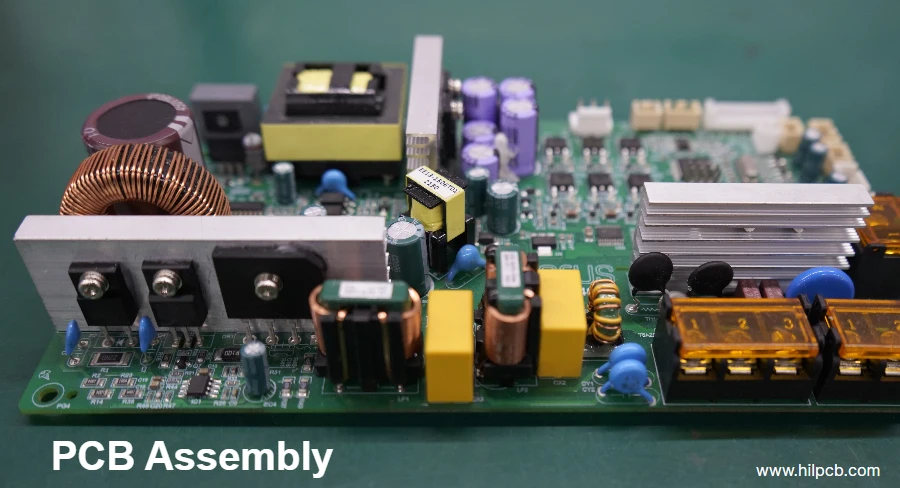
In the Industry 4.0 wave, industrial robots are reshaping manufacturing with unprecedented precision, speed, and intelligence. At the core is the motion-control system, and the PCB that carries it must survive harsh industrial conditions—continuous vibration, shock, humidity, chemical corrosion, and extreme temperatures. To ensure long-term reliability and safety, Potting/encapsulation technology has become essential. It is not merely “protective resin”; it is a multidisciplinary engineering topic involving thermodynamics, electromagnetics, and materials science. From a motion-control engineer’s perspective, this article explains how Potting/encapsulation impacts servo drives, encoder interfaces, isolation and safety circuits, and ultimately sets the performance boundary of industrial robot control PCBs.
Thermal management and stress challenges in servo-drive power loops
Servo drives are the “muscles” of industrial robots. PCB design directly affects motor response and torque accuracy. PWM drives IGBT or MOSFET power switches at tens of kHz, and accurate Dead-time control is critical to prevent shoot-through. Current sensing—via Shunt Sense resistors or Hall Sense sensors—directly affects the effectiveness of FOC (Field-Oriented Control).
Potting/encapsulation plays two roles here. First is thermal management. Power devices generate significant heat during switching; if the heat is not removed quickly, junction temperature rises, performance degrades, and permanent damage can occur. The potting compound’s thermal conductivity (W/mK) is decisive. High-thermal-conductivity compounds can efficiently conduct heat from power devices into a heatsink or enclosure, creating an effective thermal path. Poor-thermal-conductivity materials, however, “trap” heat and act as a thermal barrier—fatal for a high-performance low-loss Servo motor driver PCB.
Second is mechanical stress. During curing and subsequent temperature cycling, internal stress can build up due to CTE mismatch between the compound and the PCB base material and components—especially large BGAs and chips using Copper pillar technology. This stress can cause solder-joint fatigue, lead fractures, and even slight deformation of precision shunt resistors, affecting current-sense accuracy. Choosing a potting material with low CTE, low shrinkage, and appropriate compliance is therefore essential for long-term servo-drive reliability. In complex Servo motor driver PCB manufacturing, tight process control of potting is as important as material selection.
Signal integrity for encoder/resolver interfaces: how potting changes high-speed differential pairs
Encoders and resolvers are the robot’s “peripheral nerves”, providing precise position and speed feedback. Modern servo systems commonly use high-speed serial protocols such as EnDat 2.2 and BiSS-C. The physical layer is often RS-485 based, with signaling rates up to several MHz or higher. These high-speed differential pairs demand strict impedance control, termination, and shielding.
The key SI impact of Potting/encapsulation comes from dielectric constant (εr). Trace impedance is determined by geometry (width, spacing, height to reference plane) and the dielectric environment. Air has εr ≈ 1, while potting materials are typically εr ≈ 3–5. Once the potting compound fills the space around the traces, the effective εr increases and the impedance drops. That discontinuity introduces reflections, degrades the eye diagram, increases jitter, and can even cause communication failures.
To mitigate this, engineers must estimate the post-potting impedance shift during design. One strategy is “pre-compensation”: design the bare-board impedance slightly higher than the target (e.g., 120Ω instead of 100Ω) so it lands on the desired value after potting. This requires close collaboration with an experienced PCB manufacturer (such as HILPCB), using impedance calculators and accurate simulations based on the potting compound datasheet. Lessons from high data-integrity designs like a data-center Encoder interface board also transfer well into industrial scenarios to keep feedback links robust. Professional Servo motor driver PCB manufacturing must treat potting as part of the design, not as an afterthought.
Comparison of mainstream potting-material specifications
| Property | Epoxy | Silicone | Urethane |
|---|---|---|---|
| Thermal conductivity (W/mK) | 0.3 - 2.5 (fillable) | 0.2 - 3.0 (fillable) | 0.2 - 0.8 |
| Dielectric constant @1MHz | 3.5 - 5.0 | 2.7 - 4.0 | 3.0 - 4.5 |
| Hardness (Shore) | D60 - D90 (rigid) | A10 - A70 (soft) | A40 - D60 (medium) |
| CTE (ppm/°C) | 30 - 60 | 150 - 300 | 100 - 200 |
| Pros | High mechanical strength, strong adhesion, excellent chemical resistance | Wide temperature range, low stress, excellent electrical insulation | Good flexibility, wear resistance, relatively low cost |
| Cons | High cure stress, brittle, difficult to rework | Lower mechanical strength, weaker adhesion, possible silicone migration | Weaker high-temperature and chemical resistance |
Digital isolation in high-voltage environments: creepage/clearance and material selection
In servo-drive systems, the high-voltage power stage (often hundreds of volts DC) must be electrically isolated from low-voltage control logic (3.3V or 5V) to protect operators and sensitive control ICs. This is commonly achieved with digital isolators or high-speed optocouplers. Safety standards (such as IEC 61800-5-1) impose strict requirements on creepage and clearance across the isolation barrier.
Potting/encapsulation can help here. Filling the isolation gap with a high-dielectric-strength compound prevents contaminants and moisture from forming conductive paths on the PCB surface, improving isolation within limited space. But material choice is critical. A key parameter is CTI (Comparative Tracking Index), which measures resistance to tracking under electric fields and electrolyte contamination. Higher CTI ratings (e.g., PLC 0) indicate more reliable insulation.
For an industrial-grade PROFINET control PCB that must meet stringent safety requirements, selecting a high-CTI potting material is mandatory. The potting process must also fully fill the isolation region and avoid bubbles or voids. Such defects concentrate the electric field; in high dV/dt switching-noise environments they can trigger partial discharge, slowly eroding insulation over time and ultimately causing isolation failure. Working with a process-disciplined manufacturer like HILPCB—and using advanced methods such as vacuum potting—is essential for reliable heavy copper PCB power boards.
Brake units and energy regeneration: thermal shock and mechanical reliability
When a robot arm decelerates or a load descends, the motor operates as a generator, converting mechanical energy into electrical energy. That energy must be handled properly—typically dissipated by a brake resistor or returned to the grid through an energy-regeneration unit. Brake resistors see huge power pulses in short time windows, causing rapid temperature rises that impose severe thermal shock on the PCB and nearby components.
In this scenario, Potting/encapsulation must first provide mechanical support and vibration damping. Industrial robots operate with strong vibration, and potting secures large components such as brake resistors and relays, preventing solder-joint fatigue.
Thermal shock is the bigger challenge. High transient temperatures create major thermal stress in the surrounding compound. If the material’s Tg is too low or the compound is too rigid, repeated shocks can lead to cracking or delamination from component surfaces. Delamination not only removes mechanical support, but also creates gaps that trap moisture and contamination, introducing new reliability risks.
Therefore, potting materials in brake-resistor regions typically need both high Tg and some compliance. Silicone, with excellent high/low temperature stability, low modulus, and flexibility, is often an ideal choice. It absorbs stress from thermal-expansion mismatch and protects components and solder joints. For a reliable low-loss Servo motor driver PCB, zoned potting (different compounds for different regions) is an advanced strategy—supported by precise Servo motor driver PCB manufacturing. Selecting a high-temperature-capable high Tg PCB base material is also fundamental.
Potting/Encapsulation: key design takeaways
- Dielectric constant (εr): Directly affects characteristic impedance of high-speed traces; simulate and pre-compensate during design, especially for precision feedback systems such as data-center Encoder interface board.
- Thermal conductivity (W/mK): Determines heat-removal efficiency for power devices; critical to avoid hot spots and ensure long-term stability.
- CTE: CTE mismatch with PCB and components is a primary source of mechanical stress and can damage solder joints—especially with advanced packages such as Copper pillar.
- CTI: Indicates insulation reliability under high voltage; a core metric for meeting safety requirements (e.g., creepage distance).
- Hardness vs. compliance: Rigid materials offer better mechanical protection, while compliant materials absorb thermal shock and vibration stress; choose based on the application.
The last line of defense for EMC: how potting affects shielding and grounding
EMC is a mandatory certification requirement for industrial products. It ensures equipment operates correctly in complex electromagnetic environments and does not emit excessive interference. Servo drives are both major noise sources (high-frequency PWM switching) and sensitive victims (weak feedback signals). ESD, EFT, and Surge are common industrial disturbances.
In EMC design, Potting/encapsulation acts as a “last line of defense”. By fully encapsulating the circuit, it eliminates potential arc paths formed by dust and moisture on the PCB surface, improving immunity to ESD and high-voltage surge.
For shielding, the impact is more nuanced. Non-conductive compounds change the capacitance between the shield can and internal circuitry, potentially affecting high-frequency filtering. Conductive or semi-conductive potting materials can provide some shielding, but if poorly designed they may create new coupling paths. For example, if a conductive compound unintentionally bridges two grounds that should be isolated (such as analog and digital ground), the result can be catastrophic.
For grounding and return paths, the compound’s dielectric properties can slightly influence the path selection of high-frequency currents. While it does not alter DC ground-plane integrity, high-frequency currents prefer the lowest-impedance return. By changing the dielectric environment above a trace, potting affects its high-frequency impedance. This means that when designing an industrial-grade PROFINET control PCB with high-speed interfaces, engineers must ensure a continuous, intact reference plane to minimize return-loop area and radiated emissions. HILPCB’s experience in high-speed PCB manufacturing helps control EMC risk from the design stage.
Conclusion
Potting/encapsulation is far more than a simple “resin fill” process. It is a key technology for achieving high real-time performance, high reliability, and safety redundancy in industrial robot control PCBs under harsh environments. From servo-drive thermal management and mechanical stress, to encoder-interface SI; from high-voltage isolation barriers to brake-unit thermal-shock endurance; and finally to EMC robustness—potting permeates every corner of motion-control system design.
A successful Potting/encapsulation strategy starts with a deep understanding of application requirements and runs through material selection, PCB layout, simulation, and manufacturing process control. Whether you are developing a precision data-center Encoder interface board or a rugged low-loss Servo motor driver PCB, potting must be treated as an integral part of the system design. Partnering with an experienced manufacturer like HILPCB—with advanced capability and deep engineering know-how—and leveraging one-stop PCBA services from prototype to mass production is a competitive way to deliver exceptional performance and ultimate reliability. In the end, refined Potting/encapsulation craftsmanship puts the strongest “armor” on your product so it can face any challenge.
Common Questions
Why is potting or encapsulation more than simple mechanical protection in robot control PCBs?
Potting changes the thermal, electrical, and mechanical environment around the circuitry, so it directly influences system behavior instead of acting like a passive shell. In servo-drive and robot-control boards, it affects heat removal, vibration tolerance, insulation reliability, and long-term field durability.
Why can potting complicate signal integrity for encoder and resolver interfaces?
Precision feedback channels are sensitive to impedance shifts, dielectric changes, and parasitic coupling. Once potting surrounds the traces and components, the electrical environment changes enough that routing and simulation need to account for the compound rather than treating it as invisible.
Why is material selection critical for high-voltage isolation and reliability?
Potting compounds vary widely in dielectric constant, thermal conductivity, CTI, CTE, hardness, and moisture behavior. A poor material choice can increase stress on solder joints, reduce insulation margin, or trap heat even when the assembly initially looks robust.
Why does potting also affect EMC, grounding, and return-path behavior?
Encapsulation changes capacitive relationships, field distribution, and high-frequency current behavior around the PCB. That means shielding, ground separation, and reference-plane continuity still need careful design, or the compound may solve one weakness while introducing another.