
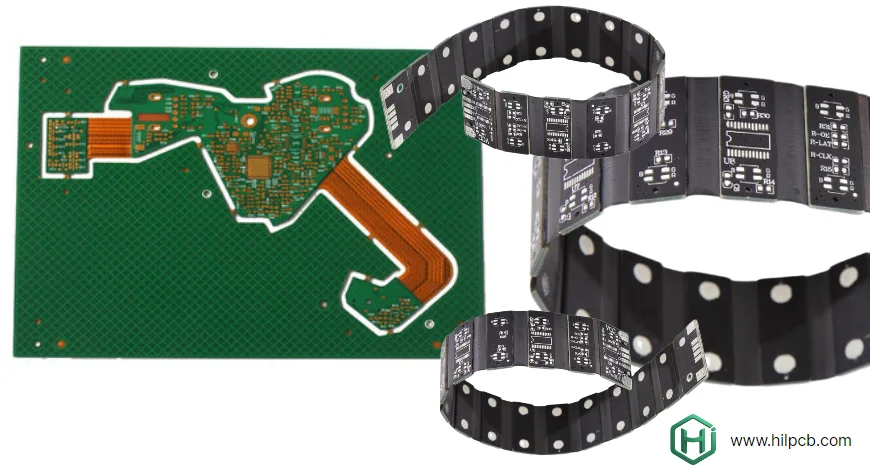
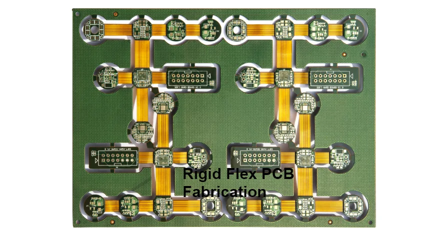
Rigid-flex PCB fabrication combines rigid component areas with flexible interconnects in one construction. The important choices are the stackup in each region, how the flex is installed or repeatedly moved, and which mechanical/electrical features must be measured. Layer count alone does not define the difficulty or acceptance plan.
For example, a folding camera or display assembly may need a conventional rigid component area and a thin flex connection, while another module needs multiple rigid islands, dense packages and controlled channels. These are application examples, not reported customer builds. Compare the complete construction with a rigid-board-and-cable alternative, including tooling, assembly access, connectors, testing and replacement strategy.
HILPCB's rigid-flex route includes FR-4/polyimide constructions, reviewed HDI microvias, coverlay/bondply control and controlled-depth routing. Prototype and production planning can connect these fabrication choices to assembly support and ordered verification.
Layer Count and Complexity Capabilities
Rigid flex PCB fabrication complexity varies dramatically from simple designs to highly complex multilayer constructions. Understanding capability ranges helps match your design to appropriate manufacturers.
Start with the supplied regions and motion
Provide a cross-section and layer map for each rigid and flex region. A hypothetical display connection might use a four-layer rigid region and a single conductive flex layer; the flex core, coverlay, adhesive and finished thickness still need definition. It is a starting concept, not a standard construction that fits every display.
For a fold-to-install part, define the installed shape and handling. For repeated movement, add motion, radius, cycle requirement, environment, support and electrical failure criteria. Copper type/thickness, conductor placement, bonded or unbonded flex layers and transition geometry affect the review. Extra layers do not automatically improve flex life.
Advanced complexity and HILPCB options
Adhesiveless PI, low-loss constructions, multiple rigid islands, sequential interconnect and via-in-pad can support particular package or channel requirements. HILPCB lists 75/75 µm standard and 50/50 µm advanced trace/space, with a reviewed 75 µm laser-microvia route. Define finished copper, via depth, annular/registration requirements and the actual region stackup together; those figures are separate options rather than a guarantee that every maximum combines.
Medical, automotive, imaging and civil communication assemblies can need different constructions and evidence. The intended equipment and qualification plan determine the requirements; an application name does not prescribe a 16-layer rigid/four-layer flex stack or establish a product approval.
For the related material and construction choices, see the flexible PCB design and manufacturing guide.
Layer Transitions and Stackup Options
Rigid flex fabrication enables various stackup architectures:
- Surface flex: Flexible circuits on outer layers of rigid-flex stackup
- Internal flex: Flexible cores within the rigid region, with the bonding and flex-exposure sequence defined for that construction
- Different rigid regions: Region-specific layers, dimensions or component areas where the fabrication flow supports them
- Multiple flex layers: Bonded or selected unbonded/bookbinder arrangements with defined layer lengths and motion
A civil communication module can use a main processing region and a smaller interface region connected by flex. Release the region boundaries and cross-sections so the fabricator can evaluate lamination, material removal and interconnect continuity. Any cost or weight comparison must include the actual parts and assembly route.

Via Technology and Interconnection Methods
Via selection follows the layer map and motion zones. A via in a rigid region and a via inside an actively bent flex region have different mechanical conditions.
Through-hole vias
Plated through-holes connect selected copper layers through the drilled stack; clearances isolate layers that must not connect. Keep plated holes, pads and mounted features out of the dynamic bend zone and define the transition/strain relief. A larger or filled via is not a universal cure for flex fatigue. If a flex-region interconnect is unavoidable, review its supported, non-bending location and verification with the design and fabrication teams.
Blind and buried vias
Blind vias connect an outer layer to selected inner layers; buried vias are enclosed within the finished construction. The drilling/plating/lamination sequence depends on the stackup. Review the subassemblies, depth, aspect ratio, registration, fill and inspection before quoting; not every blind via needs the same sequence.
HDI microvias
Laser microvias commonly cross one build-up dielectric. A stacked or staggered path uses multiple microvias and processing steps; calling it a connection of “two or three layers” does not define its geometry. HILPCB can review laser microvias and via-in-pad with the HDI route. Specify depth/diameter, landing structure, fill/cap, copper and qualification/inspection for the actual construction.
A compact camera or display module may need HDI escape in its rigid region while keeping the flex interconnect simpler. Compare the required build-up cycles and panel yield risks with the space and assembly benefit.
Controlled Impedance Fabrication
Controlled impedance is needed where the interface requires it. Rigid and flex regions can have different reference planes, dielectrics, pressed thickness, coverlay and adhesive effects. Model the released channel through the transition, not only a uniform trace in one region.
Modeling and manufacturing inputs
Provide targets/tolerances, layer references, copper profile, material constructions, finished dimensions and transition details. HILPCB lists standard ±10% and advanced ±5% with TDR for reviewed rigid-flex structures. A 100 Ω differential target, for example, needs its own approved geometry and measurement basis; it is not an automatic guarantee across every transition.
Test coupons and the actual channel
Select representative rigid and flex coupon structures and identify how transition behavior will be evaluated. TDR can verify defined impedance structures; a passing uniform coupon alone does not establish full transition loss or assembled-channel performance. Agree coupon location, method, limits and delivered results before the panel is released.
RF and mixed-material constructions
There is no universal rule that every signal above 1 GHz requires a special laminate. Evaluate frequency, edge time, length, loss, copper and geometry. RF laminates, LCP or low-loss PI may fit a particular construction, but the exact grades and bonding/process compatibility need review. For a 28 GHz module, state the measurement band, launches, fixtures, calibration and acceptance criteria rather than inferring performance from “Rogers plus Kapton.”
Material Processing Expertise
Different rigid cores, flex laminates, bondplies and coverlays have their own storage, preparation and bonding conditions. The polymer-family name is not a production recipe.
Polyimide and copper processing
Distinguish the PI film/core from the adhesive and rigid-cap resin systems. Use the material supplier's process guidance and the qualified stackup for drying, surface preparation, imaging, etching, drilling and lamination. Flex material systems include separate laminate, adhesive, bondply and coverlay products. Match their exact identities and compatible processing windows rather than selecting one temperature from the PI family name.
HILPCB's published rigid-flex process uses staged-pressure vacuum lamination, coverlay/bondply control, PI preparation and controlled-depth routing to expose flex areas. Release the actual materials and remaining-thickness/depth requirements so those operations can be planned against the construction.
Adhesive system selection
Review bondply/adhesive identity, thickness, flow, cure, thermal exposure and compatibility with every contacting material. Dynamic use, assembly reflow, environmental conditioning and rework can impose different constraints. Select the adhesive system with the released flex and rigid materials rather than solely from the application's ambient-temperature label.
Coverlay application
Conventional coverlay uses a defined film/adhesive construction with formed openings and lamination. Solder mask can use several imaging/application methods; it is not universally screen printed or interchangeable with coverlay in a bend. Specify opening registration, pad exposure, adhesive squeeze-out, edge position and inspection. These details affect soldering, connector contacts, flex motion and cleaning.
Tolerances and Manufacturing Precision
HILPCB supports qualified rigid-flex builds with 8–64 layers in rigid sections and 2–6 layers in flexible sections, and provides EM/transition-coupon engineering; these layer-count maxima are not guaranteed together and remain subject to the released stackup. Available routes include Rogers or low-loss polyimide hybrid constructions, climate-controlled material storage, vacuum baking and special etching. Dedicated programmable coverlay equipment supports ±50 μm registration. Quoted options include ±75 μm layer-to-layer registration, ±50 μm hole-position tolerance, ±25 μm trace-width tolerance, ±10% rigid-section thickness, ±8% flex-section thickness and ±12% overall assembly thickness for defined builds. Free microsections are included with production rigid-flex orders. Tolerances depend on the drawing and stackup; they are not guaranteed simultaneously across every construction.
Rigid-flex tolerances follow the actual interfaces and processes. A feature may need tighter control than on another board, but a rigid-flex label does not make every dimension inherently more precise.
Dimensional Tolerances
Dimensional and positional tolerances depend on flex construction, copper features, drilling method and inspection process. Record each tolerance on the fabrication drawing and confirm manufacturing capability before procurement.
For connector interfaces, specify mating position tolerances and verify them against the connector drawing and production capability data. Do not infer guaranteed fit from a nominal supplier tolerance alone.
Material Thickness Control
Specify rigid-region thickness, flex-region build-up, local stiffeners, adhesive and tolerances separately. Include the measurement location and whether a limit applies to a local board section or the installed assembly. Do not combine several generic percentage tolerances into an assumed fit guarantee.
For a hypothetical ±12% tolerance, a nominal 1.0 mm spans 0.88–1.12 mm and cannot satisfy a strict 1.0 mm maximum. Meeting only that upper limit mathematically requires nominal ≤ 1.0/1.12 mm; for illustration, 0.89 mm × 1.12 = 0.9968 mm. The stackup must also meet its lower thickness, electrical, mechanical and manufacturing requirements; simply changing the nominal is not a complete design solution.
Edge Quality
Define cut edges, transition geometry, tabs, routing depth and allowable damage. Cutting and handling should avoid nicks, tears, exposed copper or damage to the flex core. HILPCB’s controlled-depth routing is a construction option; specify the remaining material/depth and inspection method on the fabrication drawing.
Preview your design files using our PCB viewer tool before submission for quote, though complete design review requires quote request page submission for engineering analysis.
Quality Standards and Certifications
Select the acceptance class, revision, tests and records for the supplied board and intended equipment. Board acceptance, supplier quality-system scope and complete-product qualification serve different purposes.
Industry Standards Compliance
IPC-2223 addresses rigid-flex design, IPC-6013 qualification/performance and IPC-A-600 visual acceptability within their scopes. Confirm the revision, product class and required conformance records. Flexible material specifications depend on the selected system; IPC-4101 alone is not a universal rigid-flex material specification. State what applies rather than treating these standards as interchangeable supplier certifications.
First Article Inspection
For a first article, define the dimensional features, material identity, stackup, electrical test and any impedance or mechanical checks to be recorded. HILPCB lists E-test, AOI and dimensional checks, with TDR, microsection/transition inspection and bend or thermal testing available by the agreed route. Define specimen, conditions, quantity, limits and report scope. Static fold-to-install evidence does not establish a repeated-flex cycle result.
Traceability and Documentation
Agree the links among material lots, released revision, work order, processing and inspection/test results. Specify required certificates, lot versus unit linkage, fields and retention in the order. SMT assembly and box-build integration can add carrier/support, stiffener, enclosure and harness requirements to that same release package.
Prepare a Rigid-Flex Fabrication Order
Send Gerber/ODB++, NC drill, region-by-region stackup and outline drawings, exact material/copper/coverlay/bondply identities, quantity and acceptance requirements. Show bend lines, static or repeated motion, required radius and cycle/environment conditions, rigid-flex transitions, stiffeners, component/connector datums and critical local thicknesses.
Add via/depth/fill requirements, controlled-impedance structures, coupons and requested records. For assembly, include BOM/CPL, firmware, support/carrier restrictions, depaneling sequence and test inputs. HILPCB can review fabrication, sourcing, tooling, assembly and verification costs against the actual construction before the first panel is built.
Frequently Asked Questions
Which steps most affect a rigid-flex fabrication plan?
Material preparation, imaging/registration, coverlay and bondply placement, lamination, via formation and controlled-depth exposure of flex regions interact. The critical controls depend on the construction. Review the process flow and acceptance features across those stages.
Why can rigid-flex fabrication take longer than a conventional rigid board?
Additional core/flex preparation, bonding cycles, alignment, controlled-depth routing and inspection can add work. The schedule depends on the released stackup, material availability, tooling and capacity; it is confirmed in the quote rather than a fixed number of extra days.
How can I compare a manufacturer's capability for my construction?
Start with the region stackup, feature sizes, motion and acceptance needs. Compare the proposed flow, material options, tooling, coupons and example report fields for those requirements. HILPCB's reviewed 75/50 µm geometry routes, laser microvias, controlled-depth routing and impedance options can be evaluated against that package; a generic layer-count maximum alone is insufficient.
Which fabrication failure modes should the plan address?
Consider delamination, conductor damage near bends/transitions, registration errors, via defects and damage during cutting or handling. The design, material/process controls and chosen inspections address different risks; none is a promise that every possible failure is eliminated.
Should I order microsections or bend testing?
Use the construction and qualification plan to choose representative sections, coupons and motion tests. Microsections can document layer construction, bonding and interconnect features at selected locations. Agree sampling, test conditions, delivered records and price in the quotation.
What does a rigid-flex fabrication capability cover?
It covers the released rigid/flex regions, material and bonding process, coverlay, interconnects, flex exposure, dimensional/electrical acceptance and agreed records. Assembly support and the installed motion/thermal/equipment validation have additional requirements that should be allocated before release.