
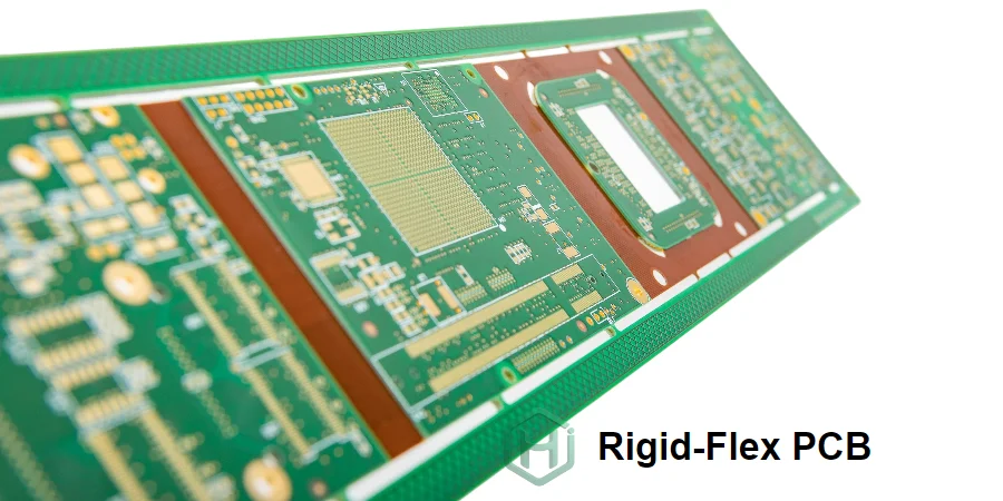
Rigid-flex PCBs combine rigid sections for component mounting with flexible circuits for 3D routing, reducing connectors, saving space, and improving reliability compared with cable-and-connector interconnects.
Successful rigid-flex production requires more than “rigid + flex”—it depends on transition-zone process control, material selection, design-for-reliability expertise, and validation testing to ensure durability across real operating conditions.
HILPCB provides custom rigid-flex PCB solutions from simple prototypes to complex multilayer rigid-flex builds with multiple flex regions, stiffeners, and controlled-impedance sections. We support aerospace, medical, industrial, and consumer applications with rapid prototyping and scalable rigid-flex PCB assembly for volume production.
Achieving Reliable Rigid-to-Flex Transitions in Complex Assemblies
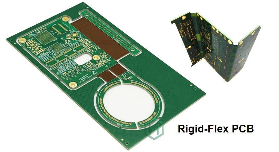
Rigid-to-flex transition zones represent critical stress concentration areas where mechanical discontinuities create failure risks under flexing, vibration, or thermal cycling. Inadequate transition design causes copper trace fractures, coverlay delamination, and plated through-hole failures that manifest as intermittent connections or complete circuit opens. Professional rigid-flex engineering ensures transition zone reliability through design optimization and validated manufacturing processes.
At HILPCIB, our advanced rigid flex pcb technology incorporates transition zone engineering principles, stress mitigation techniques, and reliability validation ensuring robust performance for high reliability rigid flex pcb applications across harsh operating environments.
Key Transition Reliability Techniques
Gradual Stiffness Transitions: Stepped stiffener designs or tapered rigid sections create gradual mechanical stiffness changes rather than abrupt discontinuities, distributing stress over larger areas and reducing peak stress concentrations in rigid flex pcb for aerospace applications.
Teardrop Pad Reinforcement: Pad-to-trace transitions using teardrop geometry (rather than perpendicular junctions) eliminate stress concentration points where traces exit rigid sections into flex, critical for multilayer rigid flex pcb reliability under repeated flexing.
Via Placement Optimization: Keeping plated through-holes minimum 50 mils from rigid-flex boundaries prevents via barrel cracking from differential expansion between rigid and flex materials during thermal cycling for custom rigid flex pcb solutions.
Coverlay Extension into Rigid Zones: Overlapping coverlay beyond rigid-flex boundaries by 50-100 mils provides mechanical reinforcement and prevents delamination at transition zones in rigid flex pcb fabrication service constructions.
Controlled Depth Milling: Precision depth routing creates rigid cavities without damaging flex layers, enabling integrated rigid-flex construction rather than separate lamination and bonding for high reliability rigid flex pcb manufacturing.
Material Expansion Matching: Selecting rigid and flex materials with similar coefficient of thermal expansion (CTE) minimizes stress from differential expansion during assembly and operation across industrial temperature ranges.
Transition Zone Validation Testing
Accelerated life testing including flex cycling (100,000+ cycles), thermal cycling (-40°C to +125°C, 1000+ cycles), and mechanical shock/vibration validates transition zone integrity for rigid flex pcb for medical devices and aerospace applications. HILPCB's rigid flex pcb manufacturer processes include microsection analysis of transition zones confirming copper continuity, adhesion quality, and absence of crack initiation sites that could propagate during service life.
Managing Layer Stack-Up Complexity in Multilayer Rigid-Flex Designs
Multilayer rigid-flex PCBs combine the complexity of both rigid multilayer stackup engineering and flexible circuit layer management, while adding transition zone considerations. Stackup design determines signal integrity performance, manufacturability, cost, and mechanical reliability across rigid and flex sections requiring careful optimization.
At HILPCB, our rigid flex pcb design service includes comprehensive stackup engineering balancing electrical requirements, mechanical performance, and manufacturing feasibility for multilayer rigid flex pcb applications ranging from 4-layer designs through 16+ layer aerospace systems.
Key Stackup Engineering Techniques
Selective Layer Flex Transitions: Not all layers need to flex—strategic selection of which layers transition into flex regions optimizes both mechanical reliability and routing efficiency in custom rigid flex pcb solutions, with unused layers terminated in rigid sections.
Symmetric Flex Construction: Balanced copper and dielectric distribution in flex sections prevents curling and maintains dimensional stability, critical for rigid flex pcb assembly service processes requiring flat circuit presentation during component placement.
Rigid Section Layer Optimization: Standard multilayer stackup design principles (controlled impedance, power distribution, signal integrity) apply to rigid sections, using proven rigid PCB technologies within advanced rigid flex pcb technology constructions.
Adhesive vs. Adhesiveless Flex: Adhesiveless polyimide construction in flex sections provides superior flex fatigue life and thermal performance compared to adhesive-based materials, essential for high reliability rigid flex pcb applications experiencing continuous flexing.
Stiffener Integration Strategy: FR4, polyimide, or metal stiffeners reinforce component mounting areas and connectors while allowing designated flex zones, with stiffener placement planned during stackup design for rigid flex pcb for aerospace mechanical requirements.
Via Technology Selection: Through-vias spanning full rigid-flex thickness vs. blind/buried vias limited to rigid or flex sections optimize layer interconnection while managing cost and complexity for cost effective rigid flex pcb manufacturing.
Stackup Documentation and Validation
Detailed stackup documentation including material specifications, dielectric thicknesses, copper weights, and transition zone cross-sections supports manufacturing execution and quality verification. HILPCB provides impedance modeling, thermal analysis, and mechanical simulation validating stackup performance before fabrication for rigid flex pcb prototype service orders, reducing iteration cycles and accelerating development timelines.
Optimizing Mechanical Flexibility in Dynamic Rigid-Flex Applications
While rigid-flex PCBs enable three-dimensional packaging, applications involving dynamic flexing (hinged devices, wearables, rotating assemblies) demand careful mechanical engineering ensuring reliability through millions of flex cycles. Inadequate mechanical design causes premature failures from fatigue, creep, or stress-induced delamination.
At HILPCB, mechanical engineering expertise integrated into rigid flex pcb for medical devices and consumer electronics ensures flex sections survive application-specific mechanical requirements while maintaining electrical performance and signal integrity.
Key Mechanical Design Techniques
Bend Radius Calculation and Enforcement: Minimum bend radius determined by total flex thickness and layer count, with design rules enforcing adequate radius in three-dimensional assembly models for custom rigid flex pcb solutions mechanical validation.
Flex Region Strain Relief: Dedicated flex lengths between rigid sections prevent overstress by providing adequate material for bending without approaching material elastic limits, critical for high reliability rigid flex pcb longevity.
Dynamic vs. Static Flex Differentiation: Different design rules apply to flex sections experiencing repeated bending (dynamic flex requiring lower stress limits) compared to one-time installation bending (static flex allowing higher stress), optimizing rigid flex pcb fabrication service for application-specific requirements.
Copper Hatching in Flex Zones: Replacing solid copper pours with hatched patterns in flex areas reduces stiffness while maintaining electrical functionality for multilayer rigid flex pcb power distribution and shielding.
Component Placement Restrictions: Avoiding components in flex zones or on flex sections eliminates assembly-induced stress and component-to-flex interactions that accelerate fatigue failures in rigid flex pcb assembly constructions.
Flex Circuit Orientation: Aligning flex direction with expected bending axis minimizes edge stresses and prevents torsional loading that can cause unexpected failure modes in rigid flex pcb for aerospace installations.
Mechanical Validation and Testing
Finite element analysis (FEA) simulates stress distribution during flexing, identifying high-stress zones requiring redesign before prototyping. Physical testing including flex endurance cycling, installation stress simulation, and accelerated aging validates mechanical design for rigid flex pcb for medical devices regulatory submissions. HILPCB's rigid flex pcb manufacturer validation ensures designs survive application environments with documented margins supporting customer reliability objectives.
Ensuring Signal Integrity Across Rigid and Flex Sections
High-speed signals traversing rigid-to-flex transitions face impedance discontinuities from material changes, reference plane transitions, and via transitions between sections. Without careful design, these discontinuities cause reflections, timing errors, and signal degradation compromising system performance.
At HILPCB, our advanced rigid flex pcb technology integrates signal integrity optimization ensuring controlled impedance continuity and minimal signal degradation across transitions for custom rigid flex pcb solutions supporting high-speed digital interfaces.
Key Signal Integrity Management Techniques
Impedance Continuity Through Transitions: Careful trace geometry and ground plane design maintain 50Ω or 100Ω differential impedance across rigid-to-flex boundaries, validated through electromagnetic simulation and TDR testing for rigid flex pcb fabrication service quality.
Reference Plane Management: Continuous ground planes through flex sections or closely coupled ground traces provide return paths for high-speed signals, essential for multilayer rigid flex pcb designs supporting USB, Ethernet, or video interfaces.
Via Transition Optimization: Minimizing via stub length and optimizing via barrel geometry reduces parasitic capacitance and inductance at transitions, critical for multi-gigabit signals common in high-speed PCB applications.
Differential Pair Routing Discipline: Maintaining tight coupling and length matching through rigid and flex sections preserves differential mode propagation and timing relationships for high reliability rigid flex pcb signal integrity.
Material Dielectric Constant Matching: Selecting rigid and flex materials with similar Dk minimizes impedance steps at transitions, particularly important for controlled impedance designs in rigid flex pcb for aerospace telecommunications applications.
Crosstalk Management: Adequate spacing between adjacent signal traces in flex sections prevents coupling, while ground stitching between differential pairs provides isolation in custom rigid flex pcb solutions carrying multiple high-speed interfaces.
Signal Integrity Validation
S-parameter measurement, eye diagram analysis, and compliance testing validate electrical performance meeting interface specifications. HILPCB provides impedance test coupons spanning rigid-flex transitions and comprehensive test reports supporting customer design validation for rigid flex pcb for medical devices requiring FDA submission documentation or rigid flex pcb for aerospace meeting DO-254 requirements.
Accelerating Development with Rigid-Flex PCB Prototype Service
Rigid-flex designs involve complex three-dimensional mechanical integration making prototyping essential for fit verification, flex region validation, and assembly process development before production tooling commitments. Traditional rigid-flex prototype lead times of 3-4 weeks create development bottlenecks limiting design iteration velocity.
At HILPCB, rigid flex pcb prototype service delivers functional rigid-flex assemblies in 10-14 days with complete process fidelity to production methods, enabling rapid mechanical validation and electrical testing for custom rigid flex pcb solutions development.
Key Rapid Prototyping Capabilities
Expedited Sequential Build-Up: Streamlined lamination scheduling and parallel processing reduce calendar time for complex multilayer rigid flex pcb constructions without compromising quality or reliability.
Design for Manufacturing Review: Expert mechanical and electrical analysis within 24-48 hours identifies rigid-flex specific design issues (transition zone violations, bend radius concerns, stackup feasibility) before fabrication start for rigid flex pcb prototype service efficiency.
Flexible Minimum Quantities: Low MOQ (5-10 pieces) makes rigid-flex prototyping economically viable for concept validation and mechanical fit-testing, with transparent pricing supporting budget planning for quick turn rigid flex pcb projects.
Material Availability: Inventory of standard rigid-flex materials and adhesive systems enables immediate production start without material procurement delays for rigid flex pcb fabrication service responsiveness.
Three-Dimensional Fit Verification: Physical prototypes enable installation testing, connector alignment verification, and flex region validation impossible with virtual design alone for rigid flex pcb for medical devices and compact electronics.
Assembly Process Development: Combined rigid flex pcb assembly service with prototype fabrication validates stiffener attachment, component placement on rigid sections, and handling procedures before volume production.
Development Velocity Advantages
Rapid rigid-flex prototyping particularly benefits products where mechanical packaging innovation differentiates competitive positioning and three-dimensional integration determines product feasibility. HILPCB's rigid flex pcb manufacturer responsiveness enables agile development with multiple mechanical iterations within compressed schedules, critical for consumer electronics, medical devices, and aerospace systems where form factor and reliability requirements evolve through development cycles.

Professional Rigid-Flex PCB Assembly Service
Rigid-flex assemblies present unique challenges beyond rigid or flex assembly alone: circuits require support during component placement, thermal profiles must account for different section thermal masses, and stiffeners demand precise placement and bonding. Without specialized capabilities, rigid-flex assembly suffers from poor yields and reliability issues.
At HILPCB, rigid flex pcb assembly service capabilities address rigid-flex specific requirements through specialized tooling, optimized processes, and quality controls ensuring assembly reliability for high reliability rigid flex pcb applications.
Advanced Rigid-Flex Assembly Capabilities
Custom Assembly Fixturing: Vacuum tooling designed for specific rigid-flex geometries holds circuits flat during component placement while supporting flex sections, preventing damage and ensuring placement accuracy for SMT assembly on complex shapes.
Stiffener Bonding Expertise: Precision alignment and controlled pressure bonding attach FR4 or polyimide stiffeners with acrylic or epoxy adhesives before component assembly, critical for multilayer rigid flex pcb requiring component support zones.
Multi-Zone Reflow Profiling: Tailored thermal profiles accounting for varying thermal mass across rigid and flex sections ensure complete solder reflow without substrate degradation for rigid flex pcb for aerospace assemblies.
Fine-Pitch Component Capability: High-precision placement equipment handles 0.4mm pitch BGAs and dense passive arrays on rigid sections while maintaining gentle handling of delicate flex areas in custom rigid flex pcb solutions.
Connector Assembly Reliability: Through-hole assembly processes optimized for rigid-flex substrates ensure robust solder joints on interconnects critical for rigid flex pcb for medical devices reliability.
Conformal Coating and Potting: Selective coating protects rigid sections while maintaining flex region flexibility, with potting services available for extreme environment protection in rigid flex pcb for aerospace applications.
Turnkey Manufacturing Integration
For rigid flex pcb OEM supplier partnerships, turnkey assembly consolidates component procurement, rigid-flex fabrication, stiffener integration, assembly, and testing under unified project management. This integration particularly benefits complex assemblies where material selection, fabrication processes, and assembly methods must be coordinated to prevent yield loss or reliability issues in high reliability rigid flex pcb manufacturing.
Rigid-Flex PCB Solutions for Aerospace and Defense Applications
Aerospace and defense electronics demand rigid flex pcb for aerospace combining extreme reliability, harsh environment survival, weight reduction, and performance validation supporting airworthiness certification. These applications justify premium rigid-flex technology through system-level benefits including reduced interconnect failures, simplified assembly, and improved maintainability.
At HILPCB, aerospace expertise includes material qualification, rigid flex pcb design service for DO-254 compliance, manufacturing controls meeting AS9100 requirements, and documentation supporting airworthiness certification processes.
Aerospace Rigid-Flex Applications
Avionics Systems: Flight control computers, navigation systems, and communication equipment use multilayer rigid flex pcb eliminating cable harness complexity while reducing weight and improving reliability in safety-critical applications.
Satellite Electronics: Space-qualified rigid-flex assemblies survive launch vibration, thermal cycling between +150°C and -180°C, radiation exposure, and vacuum conditions over multi-year missions with high reliability rigid flex pcb validated through extensive qualification testing.
Military Systems: Tactical communication equipment, weapon systems, and soldier-worn electronics employ custom rigid flex pcb solutions providing ruggedized interconnects surviving extreme environments while minimizing size and weight for portable systems.
Unmanned Aerial Vehicles (UAV): Compact electronics for drones and autonomous aircraft use rigid-flex technology enabling three-dimensional packaging within aerodynamic enclosures with cost effective rigid flex pcb economics supporting commercial drone markets.
Aerospace Quality and Certification Support
HILPCB's rigid flex pcb manufacturer quality systems include AS9100 aerospace manufacturing certification, material qualification supporting MIL-STD specifications, and traceability documentation required for airworthiness submissions. Our rigid flex pcb fabrication service provides first article inspection reports (AS9102), test data packages, and process validation documentation supporting customer certification programs for manned aircraft, unmanned systems, and space applications.
Enabling Cost-Effective Rigid-Flex Solutions
While rigid-flex technology provides system-level benefits, controlling costs remains critical for competitive products. Professional manufacturers help customers optimize total value through design collaboration identifying cost-reduction opportunities without compromising reliability or performance.
At HILPCB, cost effective rigid flex pcb manufacturing combines design optimization, process efficiency, and volume scaling delivering best economic value for rigid flex pcb OEM supplier partnerships.
Key Cost Optimization Strategies
Design Simplification: Minimizing flex regions, reducing layer count in flex sections, and using standard materials where adequate reduces complexity and cost compared to over-specified designs for custom rigid flex pcb solutions.
Selective Rigid-Flex Implementation: Using rigid-flex only where mechanical requirements demand while employing conventional rigid boards connected with flexible circuits where adequate optimizes rigid flex pcb fabrication service costs.
Standard Stackup Utilization: Using proven rigid-flex stackup configurations reduces engineering time and enables faster turnaround compared to custom stackup development for each project.
Panel Utilization Optimization: Efficient rigid-flex layout maximizing panel usage reduces material waste and per-unit costs, particularly significant for smaller assemblies in rigid flex pcb prototype service and pilot production.
Volume-Scaled Pricing: Setup and tooling cost amortization across production volumes significantly improves economics, with transparent pricing across quantity breaks supporting customer business planning.
Assembly Integration: Turnkey assembly eliminating multiple supplier margins and coordination overhead provides total cost advantages beyond piece price comparisons for rigid flex pcb assembly service.
Total Cost of Ownership Value
Beyond unit price, rigid-flex technology provides system-level value through eliminated connectors (improving reliability while reducing assembly labor), reduced testing complexity (fewer interconnects to verify), and simplified serviceability (monolithic construction vs. multiple boards and cables). HILPCB's rigid flex pcb supplier china position delivers these total cost benefits while maintaining quality and reliability standards required for medical, aerospace, and industrial applications where field failures carry significant consequences.
Conclusion
Rigid-flex PCBs enable compact 3D packaging, higher reliability by reducing interconnects, and weight savings for portable and aerospace products. HILPCB provides end-to-end rigid-flex PCB support—engineering guidance, fabrication, prototyping, and assembly—scaling smoothly from concept to volume production.
Whether your application is aerospace avionics, medical devices, wearables, or industrial equipment, we deliver custom rigid-flex builds (including multilayer structures) with validation focused on long-term reliability and cost-effective manufacturing.
Contact us for rigid flex pcb prototype service, quick turn rigid flex pcb development, rigid flex pcb design service, or volume production support—delivered with engineering excellence and manufacturing quality that accelerate your time-to-market while ensuring product success.