
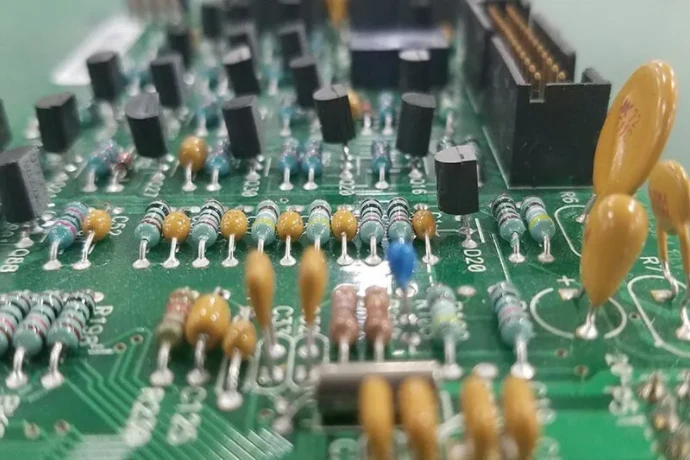
In today’s data-driven world—from data centers to edge computing—demand for faster and more reliable data transport is rising rapidly. Next-generation interfaces such as 112G/224G SerDes and PCIe Gen6 push PCB design, fabrication, and assembly to the limit for SI. In this ecosystem, one often underestimated but critical factor is the assembly process—especially for mixed-technology boards that include both SMT and THT parts. Selective wave soldering has become a key high-precision assembly method for protecting complex high-speed links and improving reliability. It not only avoids the global thermal stress of traditional wave soldering, but can directly affect the entire signal path from connector to SerDes.
From a high-speed SI perspective, this article explains how Selective wave soldering helps address ultra-high-speed link challenges. We cover its role in thermal management, impedance continuity, connector performance, and advanced via structures such as back-drilling—and why a precise assembly strategy is a prerequisite for 112G SerDes routing reliability and passing PCIe Gen6 SI checklist mass production.
What is Selective wave soldering?
Selective wave soldering is an automated, high-precision THT soldering process. Unlike traditional wave soldering that immerses the entire PCB into a solder wave, selective wave soldering uses a small, tightly controlled solder nozzle to solder only specific pins/areas. This “point-to-point” or “area selective” approach makes it ideal for modern high-density mixed-technology PCB assembly.
The process typically includes three key steps:
- Fluxing: A robotic arm or jet system applies flux precisely to the target pins to remove oxides and promote wetting.
- Preheating: Local preheat activates flux and reduces thermal shock—important for multilayer structures and low-loss materials.
- Soldering: One or more micro-nozzles move under each pin to form a small stable solder wave and complete soldering. The process often runs in nitrogen to reduce oxidation and improve joint quality.
The biggest advantage is selectivity. On server/switch/optical-module boards, expensive BGA devices (FPGA/ASIC/SerDes) often coexist with high-speed THT connectors such as SFP/QSFP-DD. Global heating in traditional wave soldering can damage heat-sensitive SMT components, while Selective wave soldering avoids this risk by design.
Why Selective wave soldering matters in high-speed designs
In the 112G PAM4 era, tiny manufacturing deviations can cause catastrophic link degradation. Selective wave soldering is valued because it directly addresses core SI and reliability pain points.
First is superior thermal-stress control. High-speed PCBs often use low-loss materials (Megtron 6, Tachyon 100G) that are electrically excellent but more sensitive to thermal stress. Selective wave soldering’s localized heating minimizes board-level thermal shock and helps prevent delamination, warpage, and micro-structure damage. This is important for maintaining the structural integrity of a complex Back-drill via design stackup, and for keeping Dk/Df stable after assembly.
Second is protection of sensitive components. In high-speed links, SerDes transceivers are the core and are typically high-density BGA packages close to THT connectors. With precise heat input, selective wave soldering reduces the risk of BGA re-melt or cold joints during secondary soldering—providing a solid physical basis for 112G SerDes routing reliability.
Finally, it delivers excellent soldering consistency. Compared with hand soldering that depends on operator skill, automated selective wave soldering provides highly repeatable results. Temperature, time, and solder volume per joint are tightly controlled, enabling consistency from prototypes to mass production—critical for passing PCIe Gen6 SI checklist mass production, which demands stable channel behavior across thousands of boards.
⚡ High-precision Selective wave soldering core process flow
For double-sided SMT high-density assembly, localized thermal management plus digital-precision fluxing helps eliminate secondary-reflow risk.
X/Y servo control enables micron-level selective spraying, significantly reducing ionic residue.
IR or hot-air selectively heats THT regions to activate flux and reduce substrate thermal stress.
Under nitrogen, independent solder nozzles solder pin-by-pin to keep Hole Fill consistent.
Controlled cooling optimizes grain structure; AOI/X-Ray verifies hole fill and clearances.
How Selective wave soldering affects connector performance
High-speed connectors (SFP, QSFP-DD, OSFP) are critical interfaces where signals leave the PCB into modules or cables. Their performance can make or break the link, and Selective wave soldering has a major impact.
A good joint forms a smooth, full solder fillet and achieves complete barrel fill. Beyond mechanical robustness, this helps maintain impedance continuity from PCB traces into connector pins. Incomplete fill or voids introduce impedance mismatch, worsen Return Loss (S11), and increase Insertion Loss (S21). When building an SFP/QSFP-DD connector routing prototype, we often use TDR to evaluate solder quality—because a small impedance dip/bump caused by poor soldering can become a link killer at 56GHz Nyquist frequency.
Selective wave soldering’s precision also enables better grounding in connector regions. By ensuring all ground pins have consistent low-impedance connection, you can improve Crosstalk and provide a stable reference plane for differential pairs. In simulation-vs-test correlation for SFP/QSFP-DD connector routing prototype, boards assembled with selective wave soldering typically match models better—proof of predictable process behavior.
Optimizing via design to match Selective wave soldering
In high-speed PCB design, vias are a major SI challenge—especially around connectors. Connector THT pins themselves behave like large via structures. A solid Back-drill via design design should consider assembly from the beginning.
Back-drilling removes unused via stubs to reduce reflections and resonance. But back-drilled structures raise soldering requirements. Selective wave soldering, with controlled heat and solder flow, helps form reliable joints without damaging the integrity of back-drilled hole walls. If temperature is too high or dwell time too long, delamination can occur at the copper-to-inner-layer interface, undermining the Back-drill via design stackup intent.
A successful Back-drill via design design strategy requires tight collaboration with the PCB manufacturer and assembly partner such as Highleap PCB Factory (HILPCB). For example, we may recommend Thermal Relief Pads on connector-pin pads to balance solder heat demand and electrical grounding. This helps solder fill the barrel while preventing excessive heat sinking into large copper pours that could cause cold joints.
Selective wave soldering design tips for high-speed PCBs
- ✔ Component spacing: Keep sufficient clearance between THT parts and nearby SMT parts (typically >3mm) for nozzle travel and thermal isolation.
- ✔ Fixture (pallet) planning: Consider pallet support and locating points in the design stage to prevent PCB deformation during soldering.
- ✔ Thermal isolation: Use appropriate thermal relief on ground/power pins so soldering heat is sufficient and uniform.
- ✔ Solder mask openings: Define openings precisely—fully exposing pads while preventing solder bridging.
Manufacturing consistency for PCIe Gen6 designs
PCIe Gen6 uses 64 GT/s PAM4 signaling and enforces extremely strict budgets for loss, reflection, and crosstalk. Any small inconsistency in manufacturing can cause link training failure or BER out-of-spec. A detailed PCIe Gen6 SI checklist mass production must therefore extend beyond design/simulation into manufacturing and assembly.
Selective wave soldering plays a key role here. Its automation keeps solder quality within tight tolerances from the first board to the ten-thousandth—critical for mass production. With hand soldering, operator-to-operator variation would create connector-region impedance drift, turning into “ghost issues” that are hard to trace in volume builds. Selective wave soldering eliminates that uncertainty and supports passing PCIe Gen6 SI checklist mass production.
112G SerDes link reliability and assembly challenges
For 112G (and beyond) SerDes links, eye openings are tiny and tolerance to Jitter, noise, and reflections is extremely low. Achieving 112G SerDes routing reliability is system engineering across the entire channel: chip, package, PCB routing, vias, connectors, and cables. Assembly—especially soldering—is a critical part of that chain.
Selective wave soldering’s gentle and controlled heating helps keep PCB material performance stable. Excessive thermal cycles can permanently shift Dk/Df, changing impedance and loss—fatal for long 112G channels. Reliable solder joints also prevent intermittent connections caused by vibration or thermal cycling; in high-speed links, these can show up as burst errors that are very difficult to diagnose. A robust assembly strategy is the foundation for long-term 112G SerDes routing reliability. As a leading high-speed PCB solution provider, HILPCB treats assembly as an inseparable part of SI design.
⚡ HILPCB one-stop high-speed PCBA solution
An engineering closed loop built for ultra-high-speed interconnect scenarios such as PCIe 6.0/7.0 and 800G networking—bridging signal simulation/design and high-precision manufacturing.
Advanced DFX engineering collaboration
Deeply engage on Back-drill via design optimization to identify stub risks; run combined reviews for impedance tolerance and assembly stress (DFA).
High-frequency material processing & fabrication
Supports low-loss laminates such as Megtron 7, validates ±5% impedance control via TDR, and uses precision back-drilling depth control to suppress reflections.
Fully digitalized assembly service
With Selective wave soldering to protect heat-sensitive components, we provide end-to-end Turnkey service from sourcing to test.
Multi-dimensional integrity inspection
In-line 3D AOI, high-resolution X-Ray, and JTAG-based functional validation ensure both physical and electrical reliability of high-speed links.
Design–manufacturing collaboration for Selective wave soldering (DFM/DFA)
To fully realize the benefits of selective wave soldering, you must plan DFM and DFA during design. This requires close communication between design engineers and the PCB manufacturer/assembler.
Key design rules include:
- Placement: Keep enough keep-out space around THT connectors for nozzle movement and to prevent heat impact on nearby SMT parts.
- Pallet planning: Complex boards may require custom pallets to support/protect the PCB during soldering; plan locating points and SMT keep-outs.
- Pad and solder mask design: Precisely define pad geometry and mask openings to prevent bridging and ensure good wetting.
At Highleap PCB Factory (HILPCB), our engineers engage early and provide free DFM/DFA review. Whether you’re assessing assembly risk for an SFP/QSFP-DD connector routing prototype or optimizing cost and reliability for mass production, we push manufacturing knowledge upstream to avoid expensive late changes and production delays.
How HILPCB ensures SI with advanced assembly technology
As a company focused on high-difficulty, high-reliability PCB fabrication and assembly, HILPCB treats Selective wave soldering as a core capability within our SMT assembly offering. With industry-leading equipment, we provide:
- High-precision control: Accurate control of nozzle diameter/height/temperature/speed, enabling fine-pitch THT soldering down to 0.5mm.
- Nitrogen protection: Nitrogen environment reduces oxidation and improves joint reliability—especially for lead-free processes.
- Flexible programming: Optimized paths and parameters per product, for both low-volume prototypes and high-volume production.
- Strict inspection: High-resolution 3D AOI and X-Ray with 100% inspection of selective-wave joints to ensure solid fill and internal integrity, meeting IPC-A-610 Class 3 requirements.
We believe excellent assembly is not just “putting parts on a board”—it is the final guardian of SI. From complex Back-drill via design stackup fabrication to precise Selective wave soldering assembly, HILPCB delivers a true one-stop solution for the 112G/224G era.
Common Questions
Why does selective wave soldering matter for high-speed SI instead of only for assembly yield?
At PCIe Gen6 and 112G SerDes speeds, small connector-region variations can directly affect reflections, loss, and link stability. That means soldering quality is part of the signal path, not just a cosmetic or throughput concern for manufacturing.
What should designers coordinate before releasing a high-speed board to assembly?
They should align on connector keep-outs, pallet strategy, pad and mask geometry, thermal exposure limits, and inspection coverage. If those details are left until production, the assembly team may be forced to work around a layout that was never optimized for stable solder joints.
Why is automated repeatability so valuable in mass production of high-speed boards?
Manual variation can create intermittent SI problems that are difficult to trace because they appear only on some builds or under stress. Automated selective wave soldering reduces that randomness and makes field performance much more consistent across prototype and volume lots.
Conclusion
In short, Selective wave soldering has evolved from a niche process into a core technology for modern high-speed, high-density PCB assembly. With unmatched precision, thermal control, and process consistency, it directly solves key SI challenges at the assembly stage. For 112G SerDes links that demand extreme performance, PCIe Gen6 systems with strict margins, and any complex design combining high-value SMT components and THT connectors, selective wave soldering is a smart choice to protect reliability, performance, and mass-production consistency.
When planning your next high-speed project, don’t treat assembly as the “last step”—treat it as a key part of the SI chain. Partnering with a provider like HILPCB with end-to-end capability from HDI PCB fabrication to advanced assembly helps ensure your innovation turns into a high-performance, high-reliability final product.