
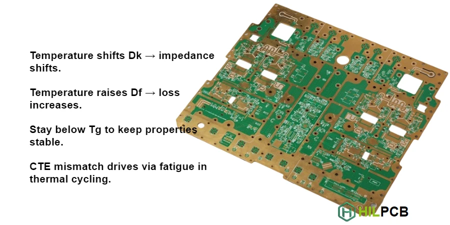
Temperature variations affect every aspect of high frequency PCB performance—dielectric properties shift, dimensions change, and material behavior can alter dramatically above certain thresholds. Designs must account for the full operating temperature range to ensure consistent performance from cold start through continuous high-temperature operation.
This guide provides comprehensive understanding of thermal effects on HF PCB material performance, from fundamental mechanisms to practical material selection for thermally demanding applications.
HILPCB offers thermally stable high frequency materials rated for extended temperature operation, with specialized RF manufacturing processes that maintain material integrity through thermal cycling.
Temperature Effects on Dielectric Properties
Dielectric constant (Dk) and dissipation factor (Df) both vary with temperature, affecting impedance and loss characteristics across the operating range.
At HILPCB, we can provide temperature-characterized material data to support designs requiring consistent performance across wide temperature ranges.
Dk Temperature Coefficient
Most materials show increasing Dk with temperature, though the magnitude varies significantly:
- Standard FR-4: Dk increases ~200-400 ppm/°C
- Low-loss FR-4: Dk increases ~100-200 ppm/°C
- PTFE materials: Dk increases ~50-150 ppm/°C
- Ceramic-filled: Can be formulated for near-zero coefficient
Impedance Impact
Since impedance depends on Dk, temperature-induced Dk change affects impedance:
ΔZ/Z ≈ -0.5 × ΔDk/Dk
Example: 200 ppm/°C over 100°C range = 2% Dk change = 1% impedance change
For tight impedance tolerance applications, specify materials with low temperature coefficient of Dk.
Df Temperature Behavior
Dissipation factor typically increases with temperature:
- Molecular mobility increases
- Loss mechanisms become more active
- Effect more pronounced in higher-loss materials
FR-4: Df may increase 20-50% over 25°C to 85°C PTFE: Df relatively stable (5-15% change)
Practical Implications
For temperature-sensitive applications:
- Characterize materials at operating temperature
- Design for worst-case (usually high temperature) loss
- Select materials with stable temperature coefficients
- Consider active thermal management for critical circuits
Glass Transition Temperature Considerations
Glass transition temperature (Tg) marks a critical threshold where polymer properties change dramatically. Operating above Tg, even briefly, can compromise reliability and performance.
HILPCB offers materials with Tg ratings from 130°C standard through 280°C+ for high-temperature applications.
What Happens at Tg
Below Tg, the polymer is rigid and glassy. Above Tg:
- Polymer becomes rubbery
- Dk and Df increase significantly
- Mechanical strength decreases
- Z-axis CTE increases dramatically (3-5×)
- Long-term reliability compromised
Tg by Material Type
| Material Class | Typical Tg |
|---|---|
| Standard FR-4 | 130-140°C |
| Mid-Tg FR-4 | 150-160°C |
| High-Tg FR-4 | 170-180°C |
| Polyimide | 250-280°C |
| PTFE | No defined Tg (stable to 260°C+) |
| Rogers RO4000 | 280°C+ |
Glass Transition Temperature Guide
Selecting Tg for Your Application
Consider all thermal exposures:
- Maximum operating temperature
- Assembly process peak temperature
- Rework temperatures
- Environmental extremes
Select Tg with adequate margin above maximum exposure—typically 25°C or more.
Lead-Free Assembly Impact
Lead-free solder requires higher reflow temperatures (245-260°C peak). Standard Tg materials may be marginal. High-Tg or better materials recommended for lead-free processes.
Coefficient of Thermal Expansion (CTE)
CTE determines how much the material expands with temperature. CTE mismatch between materials creates stress that affects reliability.
For thermally demanding applications, HILPCB offers CTE-matched PTFE laminates and ceramic-filled materials.
CTE Directions
PCB materials have different CTE in different directions:
- X-Y (in-plane): Typically 12-18 ppm/°C
- Z-axis: Higher, typically 40-70 ppm/°C below Tg, 200-300 ppm/°C above Tg
The Z-axis CTE is critical for via reliability.
CTE Matching Considerations
Copper CTE: ~17 ppm/°C
Materials with X-Y CTE near copper minimize:
- Pad lifting stress
- Via barrel stress
- Delamination risk
Z-axis CTE mismatch stresses via barrels during thermal cycling, potentially causing barrel cracks.
Material CTE Examples
| Material | X-Y CTE | Z-axis CTE (below Tg) |
|---|---|---|
| Standard FR-4 | 14-17 | 50-70 |
| Low-CTE FR-4 | 10-14 | 40-55 |
| Rogers RO4350B | 11-14 | 32 |
| PTFE/Glass | 8-12 | 24-30 |
Thermal Cycling Reliability
Applications with repeated thermal cycling require careful CTE management:
- Automotive: -40°C to +125°C cycling
- Aerospace: Extreme thermal gradients
- Industrial: High-temperature operation with off cycles
Select materials with matched CTE and perform thermal cycling qualification.
Decomposition Temperature and Long-Term Stability
Beyond Tg, decomposition temperature (Td) marks where material begins chemically degrading. Long-term exposure to elevated temperatures also affects stability even below Td.
HILPCB selects materials appropriate for your application's thermal profile including precision RF board fabrication for demanding environments.
Decomposition Temperature
Td (typically measured at 5% weight loss) indicates thermal destruction threshold:
- FR-4: Td ~310-330°C
- High-Tg FR-4: Td ~340-360°C
- Polyimide: Td ~400°C+
- PTFE: Td ~500°C+
Never approach Td in operation or processing.
Time at Temperature
Material degradation is cumulative—time at temperature matters:
- Brief excursions may be tolerable
- Extended operation at elevated temperature degrades material
- Track total thermal exposure for critical applications
Oxidation and Degradation
Long-term elevated temperature causes:
- Resin oxidation
- Copper oxide formation
- Delamination initiation
- Dk/Df drift
Conformal coating can reduce oxidation in some environments.
Material Selection for Thermal Requirements
Systematic approach to selecting materials for thermal performance requirements.
HILPCB engineering provides thermal assessment and material recommendations for demanding applications.
Define Thermal Requirements
Document all thermal exposures:
- Operating temperature range (min/max)
- Storage temperature range
- Assembly process temperatures
- Number of thermal cycles expected
- Thermal shock requirements
Match Material to Requirements
| Requirement | Material Consideration |
|---|---|
| -40°C to +85°C | Standard high-Tg FR-4 adequate |
| -55°C to +125°C | High-Tg or polyimide |
| >150°C continuous | Polyimide or ceramic-filled |
| High thermal cycling | Low-CTE, matched materials |
| Rapid thermal shock | PTFE or ceramic (stable) |
Hybrid Thermal Considerations
When combining materials in hybrid stackups:
- Match CTE between materials
- Consider differential expansion stress
- Verify bonding compatibility at temperature extremes
- Test thermal cycling reliability
Verification Testing
For critical thermal applications:
- Perform thermal cycling qualification
- Test Dk/Df at operating temperatures
- Verify impedance stability across range
- Conduct reliability testing (HAST, thermal shock)
Thermal Management in HF PCB Design
Beyond material selection, design choices affect thermal performance.
Heat Spreading
Large copper areas help spread heat:
- Ground and power planes act as heat spreaders
- Thermal vias conduct heat between layers
- Component placement affects local heating
Thermal Via Design
Connect thermal pads to internal planes:
- Via quantity based on thermal requirement
- Via diameter affects thermal conductivity
- Via fill improves heat transfer
Component Placement
Avoid concentrated heat:
- Distribute high-power components
- Provide adequate spacing for heat dissipation
- Consider airflow in placement
Interface to Heatsinks
When heatsinks are required:
- Thermal interface material selection
- Metal core PCB consideration
- Embedded coin or slug for high-power devices
Related Material Performance Topics
- High Frequency PCB Material Performance: Complete material selection guide
- Dielectric Properties of HF PCB: Dk and Df fundamentals
- Material Loss Factor in HF PCB: Loss mechanisms and minimization
- Moisture Effects on HF PCB Material: Humidity impacts
- Frequency Response of PCB Material: Wideband characterization
HILPCB Thermal Stability Services
HILPCB delivers thermally stable high frequency PCBs:
Material Selection: Guidance on materials meeting your thermal requirements from standard Tg through high-temperature polyimide and Rogers RF laminates.
Process Control: Manufacturing processes that preserve material properties through thermal processing.
Reliability Testing: Support for thermal cycling qualification and reliability verification.
Design Review: Thermal assessment as part of comprehensive DFM review.
From prototype evaluation through production qualification, HILPCB provides thermally stable high frequency PCBs for demanding applications.
Contact HILPCB for thermal requirements consultation and manufacturing quotation.
Common Questions
Why is thermal stability important in high frequency PCBs?
Temperature changes can alter dielectric properties, mechanical expansion, and loss, affecting consistent RF performance.
Which material properties matter most for thermal stability?
Stable Dk and Df, suitable Tg, low Z-axis expansion, and compatible CTE behavior are key properties.
How does temperature affect signal performance?
As temperature shifts, impedance, phase response, insertion loss, and mechanical reliability can all drift if the material system is unstable.
How do engineers improve thermal stability?
They choose materials rated for the operating range and verify performance through thermal cycling, reliability testing, and stackup review.