
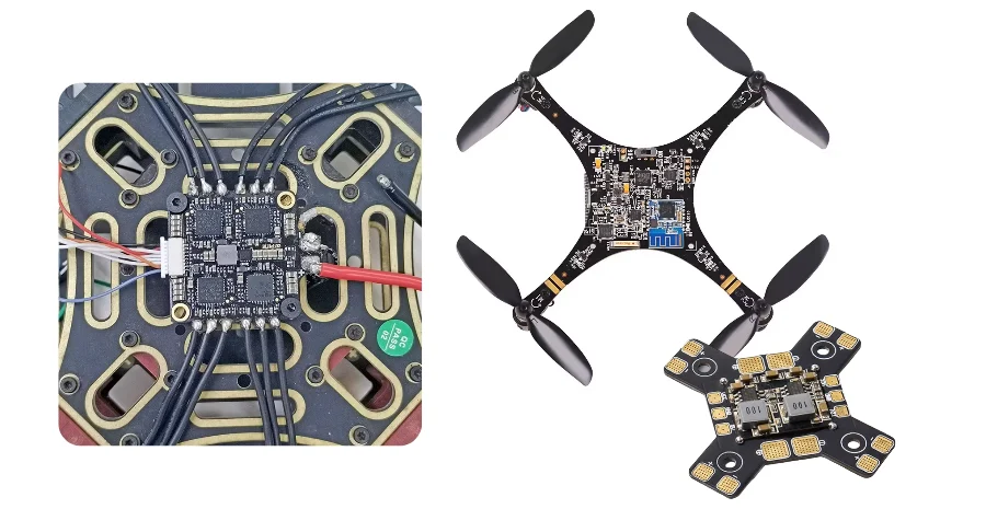
- AI drone electronics should be reviewed as an edge-compute system with strict weight, vibration, power, and RF constraints, not as a generic high-speed server board.
- The first checks are compute-module power envelope, sensor and camera interface count, vibration isolation strategy, power-rail stability, and RF antenna coexistence.
- NVIDIA Jetson Orin NX modules are published with configurable power between 10 W and 40 W, and Jetson Orin Nano modules between 7 W and 25 W, so thermal and battery decisions have to be made early rather than after layout.
- PX4 and ArduPilot both treat vibration as a flight-control risk because excessive vibration can degrade estimation quality; that means PCB mounting, connector retention, and IMU placement are part of system design.
- Most first-build failures come from noisy power rails, unstable sensor connectors, poor heat spreading around the compute module, or RF interference between control, telemetry, GNSS, and video links.
AI drone and UAV electronics combine edge computing, sensor fusion, power conversion, and wireless communication on a lightweight platform. The key engineering question is not simply whether the board can run an AI model, but whether it can do so within the aircraft's vibration, thermal, battery, and EMC limits.
Contents
- What to review first on an AI drone or UAV PCB
- Key design and validation rule table
- Early trade-off table
- How compute, vibration, and power planning affect PCB decisions
- How RF, camera, and sensor integration should be checked
- What prototype teams should lock down before release
- FAQ
- Next steps
- References
- Author and review
What to review first on an AI drone or UAV PCB
AI drone boards are often described as "smart flight controllers" or "autonomy computers," but that label is too broad to guide engineering work. The board is usually a combination of four coupled systems:- edge compute for perception, navigation, or autonomy
- flight-control and sensing hardware
- battery-fed power conversion and distribution
- RF links for command, telemetry, GNSS, or payload data
That is why the first review points are usually:
- whether the compute module's power and heat fit the airframe and battery budget
- whether vibration isolation is treated as a hardware requirement instead of only a software-filter problem
- whether CSI, Ethernet, USB, PCIe, or other fast interfaces are routed with realistic stackup and connector assumptions
- whether RF and digital sections are physically separated enough to protect GNSS and control links
- whether the build will use a rigid board, HDI board, or a mixed rigid-flex architecture
For teams still aligning stackup and connector strategy, it is usually worth reviewing high-speed PCB, HDI PCB, and rigid-flex PCB options before prototype release.
Key design and validation rule table
| Rule / parameter | Recommended range or decision method | Why it matters | How to verify | If ignored | | --- | --- | --- | --- | --- | | Compute power envelope | Start from the module's published operating modes and aircraft energy budget | AI compute changes thermal design, battery duration, and regulator sizing | Power-tree review and mission-power estimate | The board works on bench power but fails in flight duration or temperature limits | | Vibration strategy | Treat IMU mounting and board retention as hardware design items | PX4 and ArduPilot both document vibration as a control risk | Mounting review, log review, and mechanical test plan | Sensor data quality degrades before the root cause is found | | High-speed interface path | Freeze stackup and return paths before routing CSI, PCIe, USB, or Ethernet | Camera and compute links are sensitive to discontinuities and poor reference planes | Stackup review and layout review | Intermittent data errors appear during integration | | Power distribution | Separate noisy motor and payload power from sensitive logic rails | Drone systems combine switching loads with low-noise sensing | Rail-noise test plan and transient-load review | AI, RF, and sensors interfere with each other | | RF coexistence | Define antenna placement and keepout zones early | GNSS, telemetry, control, and video links compete for space and spectrum | Placement review and chamber or field test plan | Range and positioning degrade even when digital functions pass | | Thermal spreading | Tie module power modes to copper area, vias, and enclosure airflow | Published module power modes are only useful if the board can remove heat | Thermal review and instrumented prototype test | Compute throttles or fails under mission load |Early trade-off table
| Design choice | Usually stronger for | Main trade-off | What to confirm early | | --- | --- | --- | --- | | Separate AI carrier plus flight controller | Faster subsystem replacement and clearer fault isolation | More interconnects, more wiring, more weight | Connector reliability and cable management | | Integrated compute and flight board | Better mass and volume efficiency | Higher layout complexity and stronger EMI coupling risk | Heat path, grounding, and serviceability | | Rigid multilayer board | Lower cost and simpler manufacturing | Less freedom for folded packaging | Airframe volume and connector reach | | Rigid-flex architecture | Compact packaging and reduced cable count | Higher design and fabrication complexity | Bend-zone geometry and assembly handling |How compute, vibration, and power planning affect PCB decisions
The biggest mistake in this topic is to copy edge-AI module marketing language into a PCB design without turning it into a system budget.According to NVIDIA's published Jetson Orin family information, Jetson Orin NX modules are configurable from 10 W to 40 W and Jetson Orin Nano modules from 7 W to 25 W. That matters because those figures are not only software settings. They drive regulator sizing, copper spreading, heatsink design, enclosure airflow, and battery endurance assumptions.
Three review questions usually matter most.
1. Is the compute choice compatible with the aircraft power budget?
If the autonomy computer takes too much of the energy budget, the battery has less margin for propulsion, payloads, and peak transients. The board should therefore be reviewed with the same seriousness as a propulsion subsystem.
2. Has vibration been converted into a hardware requirement?
PX4 documents that flight-control boards with accelerometers and gyros are sensitive to vibration and may need anti-vibration mounting. ArduPilot's vibration guidance also treats excessive vibration as a direct cause of control and estimation problems. That means IMU location, board stiffness, connector locking, and mounting material all belong in the PCB review.
3. Is the power tree partitioned for noisy and sensitive domains?
Motor drives, payloads, camera modules, AI compute, GNSS, and IMUs do not behave like one uniform load. If the design does not split and filter these domains properly, the board becomes difficult to debug because thermal, noise, and reset problems overlap. A PCB viewer or 3D viewer review is usually useful before the first article is released.
How RF, camera, and sensor integration should be checked
AI drone electronics normally fail at the interfaces, not in the abstract compute block.The practical checks are:
- whether camera and sensor connectors are placed to minimize cable strain and vibration-driven intermittent faults
- whether CSI, USB, Ethernet, or PCIe lanes have continuous return paths and realistic connector transitions
- whether GNSS and control antennas are kept away from high-current switching nodes and fast digital edges
- whether the stackup supports both dense compute breakout and acceptable RF grounding behavior
If the design mixes compact vision hardware with telemetry and navigation radios, high-frequency PCB and high-speed PCB assumptions should be reviewed together rather than in separate workstreams. For early layout checks, Gerber viewer and PCB viewer are often the fastest way to catch placement conflicts before fabrication.
What prototype teams should lock down before release
The first prototype should answer system questions clearly, not just prove that the processor boots.A practical release checklist usually includes:
- Module power mode frozen
Tie the target compute module and operating mode to a battery and thermal budget before layout release. - Vibration and mounting assumptions approved
Decide how the board, IMU, and connectors will be retained and isolated in the real airframe. - Interface map approved
Freeze camera, sensor, RF, debug, and payload interfaces with real connector and cable assumptions. - Power-domain plan defined
Separate propulsion-adjacent noise sources from sensitive logic and RF rails. - Prototype validation plan written
Define how thermal load, vibration, RF coexistence, and sensor integrity will be checked during the first build.
If the design is still changing quickly, PCB prototype, quick-turn PCB, and turnkey assembly planning usually reduces iteration time.
FAQ
What is the first thing to check on an AI drone PCB?
Start with the compute module's power and heat budget, then review vibration, power partitioning, and RF coexistence. Those decisions usually shape the rest of the board.
Why is vibration a PCB issue and not only a flight-software issue?
Because IMUs, connectors, and mounted boards respond to mechanical input before software can compensate for it. Poor mounting and retention can corrupt sensor data at the hardware layer.
Do AI drone boards need high-speed PCB rules?
Usually yes, once the design includes camera interfaces, faster serial links, or compute modules with dense breakout and controlled-return-path requirements.
When is rigid-flex worth considering for UAV electronics?
It is usually worth considering when cable count, packaging volume, or folded mechanical routing are limiting the design. The trade-off is higher design and manufacturing complexity.
What should be proven in the first prototype?
The first build should prove thermal margin, power stability, vibration tolerance, and RF coexistence, not just basic boot or bench inference.
Next steps
If you are developing AI-enabled drone or UAV electronics, the most useful next step is usually to review compute power mode, vibration strategy, stackup, and RF placement as one system before the first build.HILPCB can support that process through:
- HDI PCB planning for dense breakout and compact packaging
- High-speed PCB review for camera and compute interfaces
- Rigid-flex PCB options when the airframe package is space constrained
- PCB prototype and quick-turn PCB support for fast validation loops
- Turnkey assembly when the prototype needs one owner across fabrication and build
- Request a quote when the stackup, interface map, and validation plan are ready