
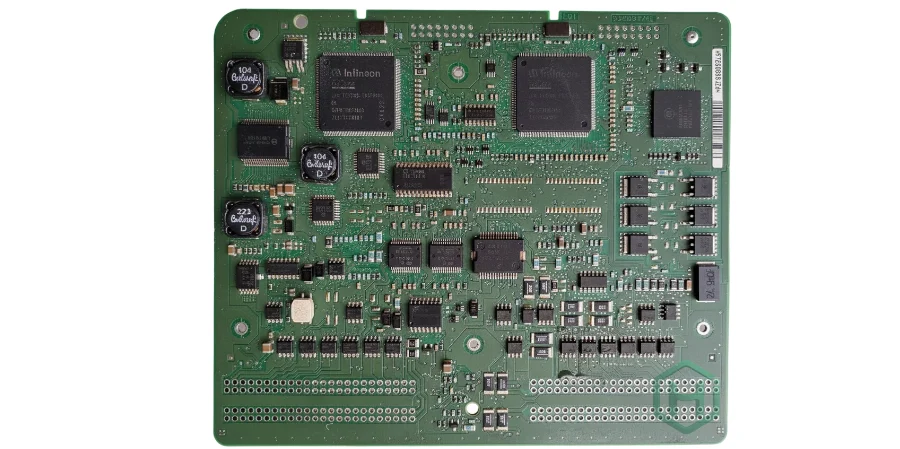
An automotive PCB solution is a controlled board or assembly construction developed for one vehicle subsystem, mounting location, lifetime profile and customer qualification plan. “Automotive grade” is not a single laminate, temperature range or certificate; the released evidence must connect design risks to manufacturing controls and system validation.
Key Takeaways
- Select the PCB technology from the subsystem and mounting environment, not from a generic automotive capability list.
- Treat IATF 16949 as a quality-management-system requirement, AEC-Q as component qualification and ISO 26262 as a functional-safety lifecycle; none alone certifies a PCB assembly for a vehicle.
- For new rigid-board drawings, verify the required IPC base standard and automotive addendum. IPC-6012FA supersedes IPC-6012EA and IPC-6012DA, but suppliers must not silently change a customer-approved revision.
- Separate bare-board evidence, assembly-process evidence, environmental tests, EMC results and vehicle-level acceptance because they prove different things.
- Put exact materials, stack-up, test methods, sampling, traceability, PPAP deliverables and change-notification rules in the RFQ.
Table of Contents
- What makes an automotive PCB solution different?
- Which automotive standards apply to PCBs?
- How do vehicle subsystems change PCB requirements?
- How should materials and stack-ups be selected?
- How should power, thermal and high-voltage risks be controlled?
- How should signal integrity, EMC and mechanics be handled?
- Which automotive PCB manufacturing evidence matters?
- What validation proves an automotive PCB is ready?
- Common automotive PCB failure modes
- Automotive PCB RFQ checklist
- Frequently asked questions
What Makes an Automotive PCB Solution Different?
The same board technology can be appropriate in one vehicle location and inadequate in another. A cabin display, wheel-speed sensor, 77 GHz radar, battery-monitoring unit and traction inverter do not share one temperature profile, voltage class, vibration input, condensation risk or safety allocation.
Start with a mission profile that identifies:
- vehicle subsystem and safety goals;
- mounting location, enclosure and cooling path;
- operating, storage and powered temperature profiles;
- humidity, condensation, fluid, dust and salt exposure;
- vibration, shock, board support and connector loads;
- supply transients, ESD and EMC environment;
- working voltage, overvoltage category and isolation boundaries;
- expected duty cycle, service life and repair strategy;
- customer-specific standards and qualification tests.
A laminate Tg value is not the maximum continuous board temperature. Likewise, a component rated to an automotive temperature grade does not prove solder-joint, via, connector, coating or enclosure reliability. Convert the mission profile into measurable requirements for the bare board, assembly and complete electronic control unit.
Which Automotive Standards Apply to PCBs?
Automotive programs use a stack of standards and customer requirements. Procurement becomes risky when a supplier collapses that stack into one “automotive certified PCB” claim.
| Document or framework | What it governs | What it does not prove |
|---|---|---|
| IATF 16949:2016 | automotive quality-management-system requirements, including customer-specific requirements and process discipline | that one PCB design meets its electrical, environmental or functional-safety requirements |
| IPC-6012F with IPC-6012FA | qualification and performance requirements for rigid printed boards used in automotive electronic interconnect environments when invoked by procurement documentation | assembled-PCBA reliability, component qualification, EMC or vehicle acceptance |
| AEC-Q100 / Q101 / Q200 | stress-test qualification for integrated circuits, discrete semiconductors and passive components respectively | bare-board or PCBA qualification |
| ISO 26262:2018 series | functional-safety lifecycle for safety-related electrical/electronic systems in series-production road vehicles | a blanket certification automatically transferred from a fabricator to the vehicle item |
| ISO 16750 series | mounting-location-dependent environmental conditions and tests for vehicle electrical/electronic equipment | EMC; ISO 16750-1 explicitly excludes electromagnetic compatibility |
| CISPR 25 and ISO 11452 series | vehicle/component emissions and immunity methods within their stated scopes | functional safety or long-term mechanical reliability |
| PPAP and customer-specific requirements | customer approval evidence for the released part and process | a universal fixed document set independent of submission level and customer rules |
The current IPC-6012FA automotive addendum was published in December 2025 and supersedes IPC-6012EA and IPC-6012DA. It is used with IPC-6012F and states that unsupplemented criteria follow IPC-6012F Class 3. That matters because some online guides still describe the automotive addendum as a generic overlay on either Class 2 or Class 3.
For a legacy drawing, use the exact revision contractually released by the customer. A newer standard may be technically preferable, but changing from DA or EA to FA can alter qualification, inspection and cost. Process the change through engineering approval instead of treating “latest revision” as an automatic substitution.
How Do Vehicle Subsystems Change PCB Requirements?
The most useful sourcing question is not “Can you build automotive PCBs?” It is “Can you build this construction, retain this evidence and support this system qualification?”
| Vehicle subsystem | Dominant PCB risks | Likely construction focus | Fabrication/assembly evidence | System-owner validation |
|---|---|---|---|---|
| ADAS camera or central compute | high-speed loss, dense BGA escape, thermal cycling, processor warpage | controlled-impedance multilayer or HDI, low-loss material where the channel budget requires it | stack-up record, TDR/VNA coupons as specified, microsections, SPI/AOI/X-ray, reflow records | link margin, image-path performance, thermal throttling, EMC and safety analysis |
| 76–81 GHz radar module | dielectric and copper variation, antenna geometry, RF transition and enclosure interaction | RF or hybrid stack-up with controlled Dk/Df, copper profile and registration | laminate/foil lot, dimensional data, RF coupon or representative channel measurement | calibrated RF performance, radome/enclosure effect and over-the-air verification |
| Battery management system | isolation, measurement accuracy, creepage contamination, long harness transients | multilayer board with defined isolation slots, material group, coating/cleanliness plan and partitioning | spacing and routing inspection, cleanliness data, hipot/insulation test only where specified, traceability | pack-level fault response, isolation monitoring, EMC, thermal and functional safety |
| Inverter, OBC or DC-DC control | high dv/dt and di/dt, gate-loop inductance, hot spots, high-voltage separation | heavy-copper or mixed-copper construction, thermal paths and controlled isolation geometry | copper/plating microsections, etch data, isolation feature inspection and current/thermal coupon if required | switching behavior, partial-discharge or dielectric tests where applicable, coolant/chassis thermal and EMC tests |
| Zonal controller or gateway | mixed power and data, connector density, automotive Ethernet/CAN, condensation | multilayer or HDI with partitioned return paths, robust connector attachment and coating plan | impedance records, connector solder inspection, coating and cleanliness evidence | network conformance, supply transient, EMC, enclosure ingress and diagnostics |
| Body, lighting or comfort module | cost pressure, LED or actuator heat, load transients and moisture | qualified FR-4, selective heavier copper or metal-backed thermal solution where justified | material identity, copper/finish data, AOI, electrical test and thermal inspection | photometric/load performance, transient immunity, thermal and environmental tests |
How Should Materials and Stack-Ups Be Selected?
Use the lowest-complexity construction that meets the released electrical, thermal and reliability margins with production variation. Over-specifying polyimide, stacked microvias, very high Tg or low-loss material can add cost and new failure mechanisms without improving the actual item.
For each candidate stack-up, evaluate:
- Thermal robustness: Tg, decomposition behavior, Z-axis expansion, moisture uptake and lead-free assembly exposure must suit the build and mission profile. High Tg helps dimensional stability but does not replace thermal analysis.
- Interconnect reliability: plated-hole aspect ratio, annular ring, copper distribution, resin flow and via structure must survive the declared thermal and mechanical loads. Avoid stacked microvias unless density requires them and the structure has a qualification plan.
- Electrical performance: use production-frequency Dk/Df information, actual copper profile and pressed dielectric tolerances for high-speed, Ethernet, SerDes, radar and antenna structures.
- CAF and insulation risk: conductor spacing, glass/resin system, hole-wall quality, cleanliness, humidity, bias and coating all contribute. A conformal coating cannot repair internal contamination or insufficient spacing.
- Manufacturability and change control: release exact core, prepreg, foil and approved alternatives. Any substitution should trigger the defined electrical, thermal and reliability review.
HILPCB can review a released high-Tg PCB, HDI PCB, high-frequency PCB or multilayer construction for fabrication feasibility. The customer or designated design authority still owns the vehicle mission profile and acceptance limits.
How Should Power, Thermal and High-Voltage Risks Be Controlled?
Copper weight alone does not establish current capacity. Trace geometry, adjacent copper, dielectric thickness, via fields, enclosure airflow, coolant interfaces, duty cycle and allowable temperature rise all affect the result. Use IPC-2152 as design guidance where applicable, then correlate the model with assembled-hardware measurements under representative loads.
For power boards, release the finished copper requirement and the features that need it. Thick external and internal copper change etch compensation, minimum spacing, resin filling and surface planarity. A heavy-copper PCB may suit bus and thermal paths, while signal layers need different geometry; mixed-copper constructions require an agreed stack-up rather than a single ounce callout.
High-voltage spacing must be derived from the applicable vehicle/OEM rules, working and transient voltage, pollution condition, material group, altitude, coating and manufacturing tolerances. Do not copy one creepage table into every EV design. Slots, barriers and coating can help, but each changes manufacturability, contamination paths and inspection access.
Define thermal reference points and limits before testing. Board-surface temperature, semiconductor junction estimate, connector terminal temperature and coolant temperature answer different questions. The PCB supplier can provide material, geometry and process evidence; the module owner must validate the complete heat path and protection behavior.
How Should Signal Integrity, EMC and Mechanics Be Handled?
Vehicle electronics combine fast edges, long harnesses, switching power and sensitive analog measurements. Design the PCB together with cables, connectors, enclosure bonds and power-entry protection rather than expecting a ground plane or shield can to solve the system later.
- Route controlled-impedance networks against continuous reference paths and define transition models for connectors, vias and packages when channel margin is tight.
- Separate high dv/dt switching loops from sensors, clocks, communications and chassis-coupling paths; minimize loop area before adding filters.
- Place transient protection and filters according to their return path and connector reference, not merely close in two-dimensional distance.
- Tie shield, chassis and signal grounds according to the system EMC strategy. An arbitrary single-point or multipoint rule is not universal.
- Model board support, connector insertion load, heavy-component mass and enclosure strain. Board thickness alone does not prevent vibration resonance or solder fatigue.
- Specify coating material, masking, thickness, cure, inspection and repair rules. Coating choice depends on environment, component compatibility and serviceability.
CISPR 25 emissions, ISO 11452 immunity and customer-specific EMC plans are normally verified on an assembled module or vehicle configuration. A bare-board impedance coupon or incoming inspection report cannot demonstrate EMC compliance.
Which Automotive PCB Manufacturing Evidence Matters?
Evidence should be selected by failure risk and linked to part, revision, lot and panel position. A long certificate list is less useful than data that can discriminate a field or qualification failure.
| Risk/control | Evidence to request | Procurement note |
|---|---|---|
| material and foil substitution | manufacturer, grade, construction, lot and certificate of conformance | define approved alternatives and requalification trigger |
| pressed dielectric and copper geometry | coupon/product microsection, finished thickness and etch measurements | define sample location and acceptance rule |
| plated holes and microvias | microsections, plating records and applicable reliability test | identify via structures separately; do not infer microvia reliability from PTH data |
| controlled impedance or RF loss | raw TDR/VNA data and coupon drawing where required | state reference planes, frequency range, de-embedding and sampling |
| solder process | paste lot, SPI, reflow profile, AOI/X-ray criteria and repair record | link records to serialized units or controlled lot |
| cleanliness and coating | test method, limits, coating batch, cure and inspection result | match evidence to flux, wash and coating process |
| traceability | raw-material lots, component date/lot codes, traveler, equipment and test result | define retention period and customer access |
| process change | PCN/change request with risk assessment and approval | include site, material, stack-up, tooling, process and sub-tier changes |
IATF 16949 certification, when required, should be verified against the current certificate’s legal entity, manufacturing site and scope. The certificate supports confidence in the QMS; it does not replace part-specific capability, control-plan or validation evidence.
What Validation Proves an Automotive PCB Is Ready?
Use a correlated evidence chain instead of one pass/fail label.
| Validation layer | What it proves | What it cannot prove alone |
|---|---|---|
| DFM and engineering analysis | the released design can be built and modeled risks are addressed | production consistency or field life |
| bare-board qualification and lot acceptance | physical/electrical attributes meet the invoked drawing and IPC requirements | solder-joint, firmware, EMC or enclosure behavior |
| assembly inspection and process validation | placement, soldering, coating and traceability are controlled | vehicle function across environment |
| module environmental and electrical tests | the assembled item behaves under defined temperature, vibration, humidity and transient profiles | all vehicle interactions or unspecified use cases |
| EMC and network conformance | emissions, immunity and communication behavior meet stated methods | functional-safety completeness or lifetime reliability |
| system/vehicle qualification | the integrated item meets customer acceptance in its intended architecture | uncontrolled future design or process changes |
Tie every result to hardware revision, software, BOM, supplier lots, test fixture, loading, environmental condition and deviation record. A prototype built with different material, copper, components or process cannot automatically qualify the production configuration.
ISO 26262 responsibilities must be allocated in the safety plan and supplier interface agreement. PCB manufacturing records may support hardware traceability, failure analysis and change control, but the design authority retains system safety requirements, diagnostic coverage, dependent-failure analysis and item acceptance unless contracts explicitly allocate them elsewhere.
Common Automotive PCB Failure Modes
| Symptom | Plausible root causes | Useful discrimination evidence |
|---|---|---|
| intermittent failure after thermal cycling | via-barrel crack, solder fatigue, connector strain or package warpage | cross-section, dye-and-pry where appropriate, X-ray/CT and thermal reproduction |
| humidity-biased leakage | ionic contamination, CAF path, inadequate spacing, coating void or enclosure condensation | cleanliness history, SIR/CAF test, sectioning and condensation-path review |
| one lot loses high-speed margin | laminate/foil change, pressed thickness, etch, registration or reflow damage | lot-specific stack-up, TDR/VNA and microsection comparison |
| resets during motor or load switching | return-path coupling, supply transient, filter saturation, grounding or firmware protection | rail and ground measurement synchronized with switching event |
| hot connector or copper region | insufficient cross-section, via bottleneck, contact resistance, assembly defect or cooling mismatch | four-wire resistance, thermal imaging and current-path review |
| vibration-dependent open circuit | unsupported mass, board resonance, cracked joint, connector fretting or enclosure strain | instrumented vibration, modal/strain review and failure localization |
| coating passes visual inspection but corrosion occurs | contamination beneath coating, wrong cure/thickness, edge coverage or material incompatibility | process records, cross-section, adhesion and chemical compatibility review |
Automotive PCB RFQ Checklist
Program and responsibility
- vehicle subsystem, mounting location, mission profile and safety allocation;
- OEM/Tier 1 customer-specific requirements, standards with revisions and order of precedence;
- prototype, qualification and production phases, quantities, forecast and service-life support;
- design authority, test owner, PPAP owner, deviation approval and failure-analysis interfaces.
Design and fabrication package
- Gerber, ODB++ or IPC-2581, drill, netlist, drawing, stack-up and revision-controlled fabrication notes;
- exact laminate/prepreg/foil, copper, surface finish, impedance/RF structures and approved substitutions;
- HDI/microvia, backdrill, via fill, heavy-copper, isolation slot and controlled-depth requirements;
- panelization, coupons, test methods, sampling, retained samples and raw-data format.
Assembly and supply chain
- BOM with manufacturer part numbers, AEC qualification/temperature grade where required, AVL and lifecycle controls;
- component moisture sensitivity, storage, bake, paste, stencil, reflow, selective/wave solder and cleaning requirements;
- SPI, AOI, X-ray, ICT, boundary scan, programming, functional test and coating scope;
- serialization, lot/date-code traceability, counterfeit controls, repair limits and record retention.
Qualification and quality deliverables
- IPC class/addendum, customer workmanship criteria and acceptance/rejection authority;
- APQP/PPAP submission level and exact requested elements, first-article and capability studies;
- environmental, transient, EMC, network and functional-safety support boundaries;
- certificate scope, control plan, process FMEA, change notification and escalation rules.
HILPCB can quote the released fabrication and turnkey PCB assembly scope, including the required coupons, inspection, traceability and documentation defined in the RFQ. Vehicle-level EMC, environmental, network, functional-safety and final product approval remain with the designated system owner unless explicitly included with agreed limits and fixtures.
Reference Standards and Specifications
- IATF 16949:2016 — International Automotive Task Force
- IPC-6012F — Global Electronics Association
- IPC-6012FA — Global Electronics Association
- IPC-A-600 — Global Electronics Association
- IPC-A-610 — Global Electronics Association
- J-STD-001 — Global Electronics Association
- IPC-2152 — Global Electronics Association
- AEC-Q100 / AEC-Q101 / AEC-Q200 — Automotive Electronics Council
- ISO 26262:2018 series — International Organization for Standardization
- ISO 16750 series — International Organization for Standardization
- CISPR 25 — International Electrotechnical Commission
- ISO 11452 series — International Organization for Standardization
Confirm the applicable revision, customer-specific requirements and procurement precedence for every program before release.
Frequently Asked Questions
What makes a PCB automotive grade?
There is no universal automotive-grade PCB label. The board must be built to a released construction and quality plan that matches its subsystem, mounting environment, customer requirements and qualification evidence.
Does IATF 16949 certify an automotive PCB product?
No. IATF 16949 governs the automotive quality-management system at a defined organization and site scope. Product acceptance still depends on drawings, control plans, customer-specific requirements, qualification results and PPAP approval where required.
Is AEC-Q100 a PCB or PCBA standard?
No. AEC-Q100 covers integrated-circuit qualification. AEC-Q101 applies to discrete semiconductors and AEC-Q200 to passive components. Their use in the BOM does not qualify the bare board or assembled module.
Should a new rigid automotive PCB specify IPC-6012FA?
IPC-6012FA is the current automotive addendum to IPC-6012F as of this update. Use it when the customer and design authority require that framework. Do not change a legacy DA or EA drawing without controlled approval.
Does high-Tg FR-4 guarantee under-hood reliability?
No. Tg is one material property. Reliability also depends on Z-axis expansion, moisture, via geometry, copper distribution, assembly exposure, mounting strain, temperature cycles and the complete module heat path.
What should be included in an automotive PCB quote package?
Provide revision-controlled design data, exact stack-up and materials, standards and customer requirements, quantities, component AVL, test and inspection scope, traceability, PPAP deliverables, change-control rules and responsibility boundaries.
Release Evidence, Not an Automotive Label
The strongest automotive PCB program connects each subsystem risk to a construction choice, process control, retained record and named validation owner. Freeze those links before quotation, keep them intact through production changes and use correlated evidence to investigate margin loss before it becomes a vehicle failure.