
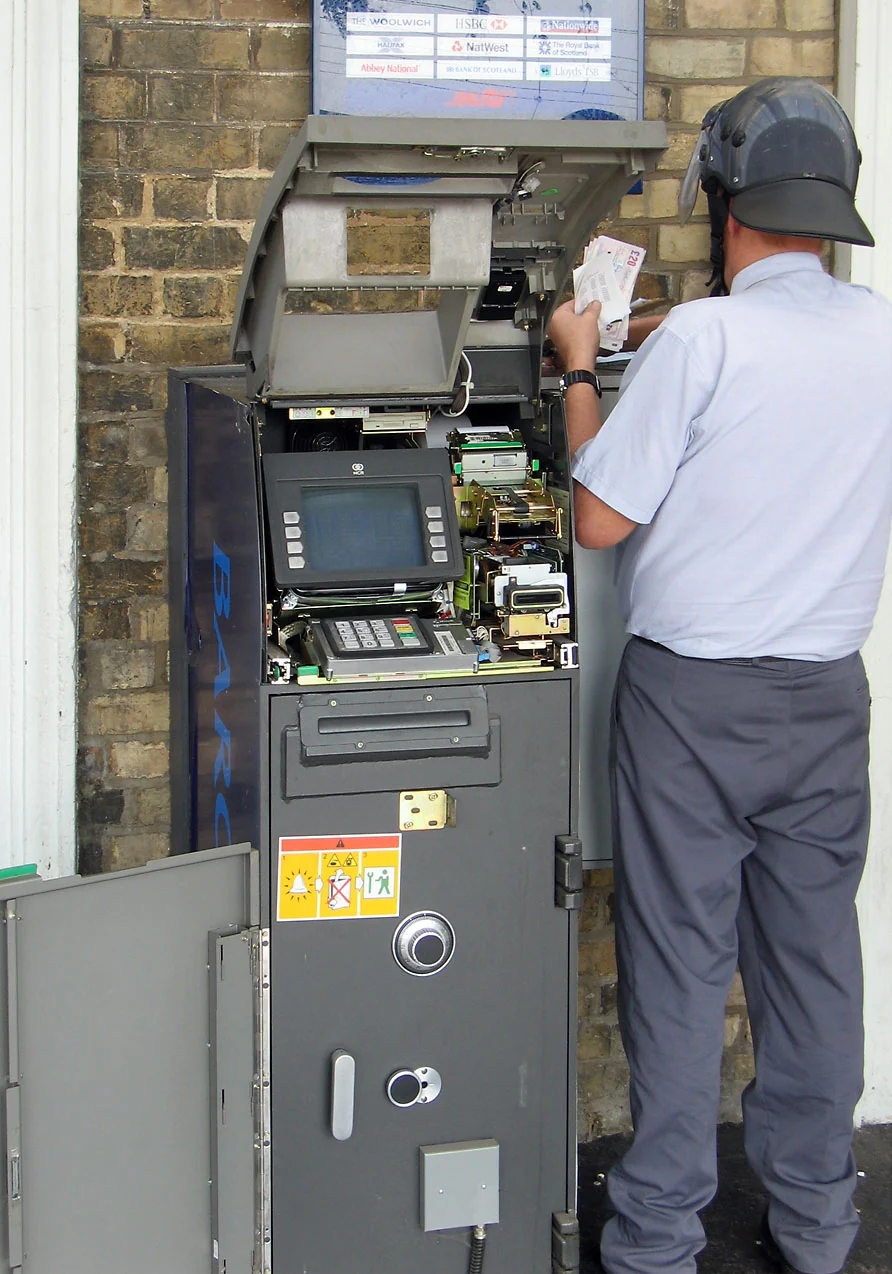
A cash dispenser PCB is the control and interface board that coordinates motors, sensors, power rails, communication links, and security circuits inside a cash-handling module or self-service terminal. It does not make an ATM or kiosk compliant by itself, but it strongly affects bill-feed accuracy, jam recovery, EMI robustness, tamper detection, serviceability, and PCBA test coverage.
For ATM, retail cash, ticket dispenser, card dispenser, coin acceptor, and check-in kiosk hardware teams, the practical design question is not only whether the board can power on. The real question is whether the PCB can survive repeated mechanical actuation, high-current motor events, noisy field wiring, sensitive sensor inputs, and security-boundary constraints without turning a transaction into a service call.
Key Takeaways
- Cash dispenser PCB design is a mixed electromechanical control problem, not a generic embedded-controller layout.
- Motor-drive current, sensor accuracy, EMI containment, and power sequencing should be reviewed as one system.
- Security wording must stay device-level. A PCB can support secure elements, tamper loops, encrypted buses, and protected zones, but payment-security validation belongs to the final terminal, secure module, and certification program.
- IPC Class 2 or Class 3 targets, high-current copper, connector retention, conformal coating, and functional test coverage should be decided before PCBA quotation.
- A useful RFQ should include not only Gerbers and BOM, but also motor loads, sensor types, duty cycle, environmental targets, test strategy, and any required traceability.
In This Guide
- What a cash dispenser PCB actually controls
- Cash dispenser PCB vs ATM PCB vs kiosk interface board
- Motor drive, power integrity and thermal design
- Sensor interfaces and bill-path detection
- EMI, high-speed communication and grounding
- Security boundaries and tamper-aware layout
- Manufacturing and PCBA test planning
- Common failure modes in cash-handling PCBs
- Cost drivers and design tradeoffs
- RFQ checklist for cash dispenser PCB projects
- Why work with HILPCB
- Reference standards and specifications
- FAQ
What a cash dispenser PCB actually controls
A cash dispenser PCB is usually responsible for a narrow but demanding part of the terminal: moving physical media accurately while reporting its state to the host controller. In a bank ATM, it may sit inside a cash cassette or dispenser module. In a retail automation terminal, it may coordinate notes, coins, tickets, vouchers, or cards. In a kiosk, it may share the enclosure with payment, display, network, printer, and access-control boards.
The PCB typically has to coordinate five board-level functions.
| Function area | Typical circuitry | PCB review focus | What can go wrong |
|---|---|---|---|
| Motor drive | Brushed DC, stepper, BLDC or solenoid drivers | Current path, flyback control, copper width, thermal vias, connector rating | Brownout, overheating, reset during dispense, motor stall damage |
| Sensor input | Optical interrupters, reflective sensors, magnetic sensors, thickness or position sensors | Analog filtering, shielding, ADC reference quality, routing away from motor currents | False bill count, double feed, jam not detected, false reject |
| Host communication | USB, UART, RS-232, RS-485, Ethernet, CAN or vendor-specific links | ESD protection, impedance where required, isolation posture, connector placement | Communication dropouts, corrupted status reports, firmware update failure |
| Power management | 24 V / 12 V motor rails, 5 V and 3.3 V logic, isolated rails where needed | PDN impedance, sequencing, inrush, load-step response, heat spreading | MCU reset, sensor drift, motor torque instability |
| Security support | Secure element interface, tamper loop, enclosure switch input, protected signal zone | Boundary routing, internal trace routing, test-point control, secure-zone documentation | Tamper signal bypass, probe exposure, unprotected key or status lines |
Cash handling is unforgiving because mechanical and electrical margins interact. A board may look stable during bench testing but fail when a motor starts under load, a bill skews in the feed path, or a long cable injects noise into a sensor reference. That is why a useful cash dispenser PCB review must include motor current, sensor timing, ground return, connector stress, and test coverage together.
The board also needs realistic claim boundaries. The PCB can support transaction security and tamper detection, but it should not be described as “PCI compliant” or “ATM certified” on its own. Payment-security approval depends on the secure device, firmware, key management, terminal integration, and certification route, not only the bare board or assembled control PCB.
Cash dispenser PCB vs ATM PCB vs kiosk interface board
Search terms in this category often overlap. Cash dispenser PCB, ATM PCB, ticket dispenser PCB, card dispenser PCB, coin acceptor PCB, and check-in kiosk PCB do not describe the same design burden. They share reliability and PCBA concerns, but the port mix, sensor stack, motor power, enclosure constraints, and security context can differ significantly.
| Board type | Main job | Common PCB challenges | Security/compliance boundary |
|---|---|---|---|
| Cash dispenser PCB | Feed, separate, count and dispense banknotes or similar media | Motor-drive noise, bill-path sensors, jam detection, power dips, connector wear | Supports secure transaction hardware but does not prove terminal compliance |
| ATM PCB | Controls or interfaces with ATM subsystems such as cash handling, card reader, display, keypad and network | Mixed high-current, secure, display and communication zones | Device-level and payment-network requirements must be handled at terminal level |
| Ticket dispenser PCB | Drives ticket/voucher feed, cutter and presence detection | Motor/solenoid transients, cutter load, optical sensor contamination | Usually lower payment-security burden unless tied to payment credentials |
| Card dispenser PCB | Feeds, detects and sometimes encodes cards | Motor control, card-position sensing, ESD at user-accessible slots | Security depends on card data handling and host integration |
| Coin acceptor PCB | Detects coin properties and routes accepted/rejected coins | Analog sensing, vibration, contamination, mechanical shock | Validation depends on the currency/acceptance module and system logic |
| Check-in kiosk PCB | Interfaces display, printer, scanner, payment and network modules | USB/Ethernet robustness, power distribution, enclosure cabling | Privacy and payment security are system-level issues |
This distinction matters because the best PCB architecture depends on the physical media path. A cash dispenser board usually needs stronger motor-current planning than a simple display controller. A coin acceptor board may need more analog sensing discipline. A check-in kiosk controller may be more about cable management, USB/Ethernet reliability, ESD at user-facing ports, and modular assembly.
Motor drive, power integrity and thermal design
Motor drive is the first place cash dispenser PCBs stop behaving like ordinary embedded boards. Rollers, belts, diverters, shutters and reject paths can require short high-current pulses, rapid reversal, braking, or stall detection. If the PCB copper, connector, driver package and power supply are not reviewed as one current path, the board may pass a simple functional test and still fail in field duty.
The motor-power zone should be physically and electrically separated from the sensor and secure-control zones. High-current loops should be short, wide, and referenced to a predictable return path. Flyback diodes, TVS clamps, snubbers, current-sense resistors and bulk capacitors should be placed where they actually control the transient source, not where they are merely convenient for routing.
Power-integrity review should look at load steps, not only nominal voltage. A dispenser motor may pull down a rail exactly when the MCU is reading sensor state or writing a transaction log. The layout should keep motor return current away from ADC references, sensor grounds, crystal/clock circuits, and secure-device rails.
| Design item | Practical review point | Typical manufacturing implication |
|---|---|---|
| Motor rail copper | Confirm trace width, copper weight and via current capacity against peak and stall current | Heavy copper or localized copper pours may be needed |
| Driver heat path | Provide thermal vias, copper spreading and airflow or chassis conduction where available | Pad design, solder void control and assembly profile matter |
| Inrush and load step | Size bulk capacitance and rail separation for motor start/stop events | Functional test should include loaded motor cycles |
| Current sensing | Keep sense traces Kelvin-routed and away from switching nodes | Test access may be required for calibration or validation |
| Rail sequencing | Prevent logic or secure-device rails from collapsing during motor events | Bring-up and production test should verify worst-case sequence |
| Connector rating | Check current, retention, insertion cycles and cable strain relief | Through-hole or reinforced SMT connectors may be preferred |
Thermal management should be described as a board-support function, not as a universal lifetime promise. Driver IC junction temperature, copper area, enclosure airflow, duty cycle, ambient temperature and mechanical load all change the final result. For high-current dispenser modules, heavy copper PCB and high thermal PCB options can be reviewed when current density or heat spreading becomes a release risk.
Sensor interfaces and bill-path detection
Cash handling depends on accurate state detection. A dispenser does not only ask whether a motor turned. It needs to know whether a bill was picked, whether two sheets overlapped, whether the bill reached the right gate, whether a reject path was used, and whether the customer-facing outlet is clear. Those decisions often depend on sensors operating near motors, cables, lights, dust, static discharge and mechanical vibration.
At board level, the key is to protect weak or timing-sensitive sensor signals from power noise and ground movement. Optical sensors and interrupters may look digital, but their thresholds can drift if the supply is noisy or the return path is shared with motor current. Analog thickness or media-detection sensors are even more sensitive because a small offset can become a wrong count or false jam.
| Sensor/interface type | Board-level risk | PCB control method |
|---|---|---|
| Optical interrupter | False transitions from noise, contamination or LED aging | Stable supply, local filtering, threshold margin, test access |
| Reflective sensor | Background reflectance variation and ambient light sensitivity | Shielded routing, controlled LED drive, calibrated threshold path |
| Thickness or overlap sensing | Small signal buried in motor noise | Analog partitioning, quiet reference, guard/ground strategy |
| Encoder or Hall sensor | Missed pulses during motor events | Clean digital routing, debounce/filter plan, return-path continuity |
| Door/cassette switch | Long cable ESD and contact bounce | ESD protection, RC filtering, robust connector pinout |
| Customer outlet sensor | User-accessible ESD exposure | Protection at connector entry and chassis-aware grounding |
The PCB cannot solve all bill-path problems. Roller wear, cassette tolerance, software timing, sensor calibration and paper quality all matter. But the board can either make those variables measurable or make them invisible. A strong release package identifies which sensor lines need shielding, which thresholds require calibration, which connectors are user- or service-accessible, and which signals deserve production-test coverage.
EMI, high-speed communication and grounding
Cash dispenser electronics sit in a noisy environment. Motors, solenoids, long harnesses, contact switches, displays, payment modules and external network connections can all inject noise. EMI design is therefore not a cosmetic compliance step at the end of the project. It shapes the board floorplan from the beginning.
The first rule is to keep noisy current loops and quiet measurement loops from sharing the same return path. The second rule is to protect external cable entry points before transients travel deep into the board. The third rule is to treat chassis, shield and logic ground as a deliberate strategy rather than a last-minute copper pour.
| Interface | Typical risk | PCB review action |
|---|---|---|
| USB | ESD at service/user ports, common-mode noise, cable radiation | ESD array near connector, controlled pair routing, shield strategy |
| Ethernet | Surge/ESD, magnetics placement, cable emissions | Transformer/magnetics zone, chassis reference, differential routing |
| RS-232 / RS-485 | Long harness transients and ground offset | TVS protection, optional isolation, termination and biasing review |
| CAN | Common-mode stress and cable ESD | TVS, common-mode choke where appropriate, termination access |
| Sensor harness | Motor noise and intermittent connection | Filtering, keyed connector, separation from motor cable |
| Motor harness | High di/dt and inductive kick | Clamp path, connector current rating, wide return path |
High-speed language should stay realistic. Not every cash dispenser board needs server-grade differential-pair complexity, but USB, Ethernet, camera/contact-image-sensor modules, and modern SoC links may require controlled impedance and proper return-path design. When these interfaces become central to the architecture, high-speed PCB review is the right route.
For EMC planning, the PCB should support system testing such as electrostatic discharge, electrical fast transient, and surge immunity where relevant. It should not claim system EMC pass status unless the final product has actually been tested in its enclosure, harness, power supply and operating mode.
Security boundaries and tamper-aware layout
Security in cash-handling systems must be handled carefully. A PCB can support the security architecture, but it does not replace a certified secure device, key-management process, payment application, or terminal-level assessment.
A practical cash dispenser PCB may include secure-element interfaces, encrypted communication paths, tamper switch inputs, intrusion-detection loops, protected boot signals, security-zone shielding, and controlled test-point exposure. Those are valid board-level design topics. What should be avoided is claiming that the PCB itself is PCI PIN compliant, PCI PTS approved, or certified for payment transactions.
| Security feature | What the PCB can support | What still needs system/device validation |
|---|---|---|
| Secure element or crypto module | Clean power, short protected traces, controlled test access | Key management, firmware, approved secure hardware path |
| Tamper switch or loop | Reliable routing, pull-up/pull-down stability, connector protection | Enclosure attack testing and response logic |
| Secure boot support | Flash routing, reset control, programming access control | Firmware signing, lifecycle control and update process |
| Protected bus | Internal routing, avoid exposed test pads, controlled connector access | Protocol security and application-level encryption |
| Service/debug port | Lockable access, documented production programming flow | Field service policy and access authorization |
| Physical anti-probing | Inner-layer routing and reduced exposed nodes where justified | Threat model and certification-program evaluation |
The correct public message is that HILPCB can manufacture and assemble boards that support secure terminal architecture. Final compliance depends on the terminal developer's threat model, secure component selection, firmware, key handling, enclosure design, and applicable certification program.
Manufacturing and PCBA test planning
Cash dispenser PCBs should be designed for manufacturing and service before the first production build. The board often contains high-current drivers, fine-pitch logic, connectors under mechanical stress, sensor thresholds, firmware programming points and security-sensitive areas. That combination makes late test planning expensive.
A good manufacturing package should define the board class target, surface finish, copper weight, connector technology, coating requirement, test fixture access and any traceability needs. If the product will operate in retail or banking equipment for long service intervals, accepting a vague “standard PCB” build is rarely a good release posture.
| Production control | Why it matters | Typical evidence to request |
|---|---|---|
| DFM review | Prevents trace/space, annular ring, solder mask and connector issues | DFM report before fabrication |
| AOI and X-ray where needed | Detects solder bridges, opens, BGA/QFN risks | Inspection records or agreed quality plan |
| Electrical test | Confirms bare-board continuity and isolation | Flying probe or fixture test record |
| Functional PCBA test | Verifies power rails, motor outputs, sensor inputs and communication | Test procedure and acceptance limits |
| Loaded motor test | Reveals rail droop, thermal rise and transient behavior | Fixture design and cycle profile |
| Sensor calibration support | Reduces false accepts, rejects or jams | Calibration points and firmware/test flow |
| Ionic cleanliness / coating | Helps avoid leakage and corrosion in harsh use | Cleaning and coating specification if required |
| Traceability | Supports field failure analysis and controlled rollout | Lot, panel, BOM and serial-number records |
For boards with fine-pitch BGAs, controlled impedance, high-current sections or dense connectors, turnkey assembly is often more practical than splitting fabrication, procurement, SMT and test across multiple vendors. The issue is not only convenience. It is that motor drive, sensor thresholds and communication stability need to be validated on the assembled board, not only on the bare PCB.
Common failure modes in cash-handling PCBs
The most expensive cash dispenser PCB failures often look mechanical at first. A bill jams, a card does not eject, a cassette reports the wrong state, or the terminal goes offline. But the root cause can be electrical: rail droop, EMI, connector intermittency, sensor threshold drift, or weak solder joints under vibration.
| Failure mode | Likely board-level cause | Prevention during review |
|---|---|---|
| Random MCU reset during dispense | Motor inrush pulls down logic rail or injects ground noise | Separate power domains, bulk capacitance, star/controlled return path, loaded motor test |
| False double-feed or false jam | Sensor threshold disturbed by noise, contamination or weak reference | Analog partitioning, filtering, calibration support, sensor test points |
| Motor driver overheating | Inadequate copper area, poor thermal-via design or unrealistic duty cycle | Thermal simulation/review, copper spreading, driver derating, duty-cycle validation |
| Communication dropout | ESD, cable transients or poor connector shielding | Protection at entry, cable-ground strategy, interface-specific testing |
| Intermittent service faults | Connector vibration, weak solder joints or harness strain | Connector retention, through-hole/reinforced options, strain-relief planning |
| Corrosion or leakage | Flux residue, humidity or uncoated exposed circuits | Cleaning requirement, conformal coating, material/environment review |
| Tamper signal instability | Long noisy loop or exposed test/debug point | Filtered tamper input, protected routing, documented service access |
| Field update failure | Weak debug/programming access control or unstable power during update | Programming fixture plan, secure update flow, rail hold-up review |
This type of table is usually more useful than a generic “high reliability” claim. It gives the hardware team something to verify and gives procurement a clearer basis for comparing PCB/PCBA suppliers.
Cost drivers and design tradeoffs
Cash dispenser PCB cost is driven less by the board outline alone and more by the combination of current, density, security, test, and assembly requirements. A cheap bare board can become expensive if it causes service calls, false jams, or field replacement.
| Cost driver | Why it increases cost | When it is justified |
|---|---|---|
| Higher copper weight | More material and tighter fabrication control | Motor current, thermal spreading or low voltage drop requires it |
| HDI or fine pitch | More process steps and yield sensitivity | Compact control boards, BGA/SoC packages or dense connectors need it |
| Controlled impedance | Stackup and trace control add engineering and process burden | USB, Ethernet, high-speed sensor or image links require it |
| Rigid-flex or flex interconnect | More complex materials and fabrication | Moving modules or compact kiosk layouts need connector reduction |
| Conformal coating | Adds process and inspection steps | Humidity, dust, cleaning chemicals or long service life justify it |
| Security-oriented layout | More layers, internal routing and access control | Secure-zone routing or anti-probing posture matters |
| Functional test fixture | Upfront engineering cost | Motor, sensor and communication behavior must be verified in production |
| Traceability | Documentation and serialization overhead | Financial, retail or field-service programs require controlled records |
The best cost decision is usually not the lowest PCB price. It is the lowest avoidable field-failure risk for the required service life. If the dispenser board drives motors, reads weak sensors, and communicates with payment or terminal-control systems, the RFQ should compare suppliers on DFM quality, assembly control and test capability, not only on square-centimeter board price.
RFQ checklist for cash dispenser PCB projects
A useful cash dispenser PCB RFQ should let the manufacturer understand the electrical, mechanical and validation burden. Sending only Gerbers and a BOM is often not enough.
Design files
- Gerber or ODB++ files
- Drill files and board outline
- Stackup requirement and copper weight target
- Controlled impedance table, if any
- Assembly drawings and pick-and-place files
- BOM with approved manufacturer part numbers and alternates
- Schematic or redacted block diagram for DFM/DFT review where possible
Electrical and mechanical requirements
- Motor type, voltage, peak current, stall current and duty cycle
- Sensor types and sensitivity requirements
- Power input range and rail sequencing requirements
- Communication interfaces and connector pinouts
- Cable length, shield strategy and user/service-accessible ports
- Expected operating temperature, humidity, vibration and contamination exposure
- Any enclosure, chassis or grounding constraints
Security and compliance context
- Secure element or tamper-loop routing requirements
- Debug/programming access policy
- Traceability or serialization requirement
- Payment-security boundary owned by the terminal designer
- EMC, ESD, EFT or surge test plan that the PCB must support
- Required IPC class target and inspection criteria
Production and test expectations
- Prototype quantity and mass-production forecast
- Bare-board electrical test requirement
- SMT, through-hole and box-build scope
- Functional test fixture requirements
- Loaded motor and sensor-calibration test steps
- Conformal coating, cleaning or packaging requirements
- Failure-analysis and reporting expectations
Why work with HILPCB
HILPCB supports cash dispenser, ATM, retail kiosk, ticket dispenser, card dispenser and coin acceptor electronics with board fabrication and PCBA manufacturing routes matched to electromechanical control hardware.
The strongest fit is not a generic promise of “financial-grade quality.” It is the ability to review the board as a mixed-power, mixed-signal and mechanically stressed PCBA.
| Need | HILPCB support path |
|---|---|
| Motor-drive current and heat | Heavy copper, thermal-via review and power-zone DFM |
| Compact controller layout | HDI PCB and fine-pitch assembly support |
| High-speed terminal interfaces | High-speed PCB stackup and routing review |
| Durable connector and harness assembly | SMT, through-hole and reinforced connector assembly options |
| Functional validation | Turnkey assembly with fixture planning support |
| Prototype-to-production handoff | Small-batch builds, BOM sourcing, DFM/DFA and scalable PCBA workflow |
If the design already contains sensitive sensor inputs, motor driver heat, secure-zone routing or multiple external ports, share the full manufacturing package early. That gives the engineering team enough context to catch current-path, return-path, connector and test-access issues before they become production defects.
Reference standards and specifications
The following references are useful as context for cash dispenser PCB and terminal-development programs. They should not be used as standalone claims that a PCB is compliant, certified or payment-approved.
- IPC-A-600
- IPC-A-610
- IPC-6012
- IPC-2221
- IEC 61000-4-2
- IEC 61000-4-4
- IEC 61000-4-5
- ISO 9564
- PCI PIN Security Standard
- PCI PTS POI Security Requirements
- ISO 9001
FAQ
What is a cash dispenser PCB?
A cash dispenser PCB is the board that controls motors, sensors, power rails, communication links and security-support circuits inside a cash-handling module. It helps the dispenser feed, count, detect and report media movement reliably.
Is a cash dispenser PCB the same as an ATM PCB?
Not exactly. A cash dispenser PCB usually controls the cash-handling module, while an ATM PCB can refer to many terminal boards such as the main controller, card reader interface, keypad interface, display controller, network board or power board.
Can a PCB be PCI PIN or PCI PTS compliant by itself?
No. The PCB can support a secure terminal design, but PCI PIN and PCI PTS approval depends on secure devices, cryptographic handling, firmware, enclosure, integration and certification testing. Do not claim payment-security compliance unless the validated scope is clear.
Which PCB problem most often causes dispenser faults?
Many faults come from interaction between motor current and sensor or logic stability. Rail droop, noisy grounds, poor transient suppression and weak connector retention can appear as jams, false counts or communication errors.
Do cash dispenser PCBs need heavy copper?
Some do. Heavy copper is useful when motor current, voltage drop or thermal spreading exceed what a standard copper weight can support. The decision should be based on peak current, stall current, duty cycle and thermal limits.
Why are functional tests more important than bare-board tests here?
Bare-board electrical testing confirms continuity and isolation, but it cannot prove motor behavior, sensor threshold stability, communication robustness or security-zone response. Cash-handling boards usually need PCBA-level functional testing.
What should I send for a cash dispenser PCB quote?
Send Gerbers or ODB++, BOM, stackup, assembly drawings, motor current data, sensor list, interface list, environmental targets, security boundary notes and any functional-test requirements. The more complete the RFQ, the more useful the DFM and cost feedback will be.
Next step
If your cash dispenser, ATM, card dispenser, ticket dispenser, coin acceptor or retail kiosk board is already carrying motor-current risk, sensor noise, secure-zone routing or uncertain test coverage, treat the PCB package as an electromechanical control system before releasing it.
Send the Gerber package, BOM, motor-load profile, sensor list and test expectations to [email protected], or upload the files through the Quote page. HILPCB can review the design for manufacturability, assembly risk, current-path integrity, connector robustness and PCBA test planning before prototype or production build.