
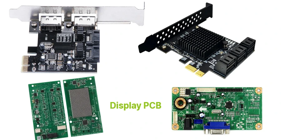
- A color TFT display PCB should be reviewed as the control and support board for a TFT-LCD system, not as a generic "screen board."
- The first engineering checks are panel interface, timing path, backlight method, power sequencing, outdoor readability requirement, and connector or flex reliability.
- TFT-LCD products still depend on clean signal routing, stable rails, and a realistic optical-electrical stack review even when the panel module looks standardized.
- Most failures come from interface mismatch, weak return paths, noisy backlight power, poor outdoor-readability assumptions, or releasing the prototype without a real debug path.
- Early success usually depends on matching panel type, interface, backlight architecture, and manufacturing route before the first prototype build.
A color TFT display PCB is the board or board set that delivers image data, control timing, power, and backlight support to a TFT-LCD module. The practical design question is not only whether the panel can light up, but whether the interface, power behavior, backlight method, and outdoor readability target are aligned well enough for stable production use.
Contents
- What to review first on a color TFT display PCB
- Key design and validation rule table
- Early engineering trade-off table
- How interface choice affects routing and bring-up
- How backlight and outdoor-readability strategy affect the board
- What prototype and assembly teams should freeze before release
- FAQ
- Next steps
- References
- Author and review
What to review first on a color TFT display PCB
Color TFT and OLED should not be treated as the same PCB problem. A TFT-LCD panel depends on a liquid-crystal layer, timing control, and a backlight system, and Sharp's TFT LCD technical materials also show that different transmissive and transflective variants change the outdoor-visibility and power trade-off. That means the PCB has to be reviewed against the real panel class and real use environment rather than against broad "display technology" language.The first review points are usually:
- whether the panel interface is eDP, MIPI DSI, RGB, LVDS, or another format and whether the host can support it cleanly
- whether the routing path through board, connector, and flex keeps reference continuity for the actual data rate
- whether the product needs transmissive, transflective, or stronger high-brightness behavior for the use environment
- whether the backlight power stage is isolated well enough from timing and control sections
- whether the prototype includes enough measurement access to debug rails, reset, brightness control, and interface activity
For denser display-control boards, it is usually worth checking high-speed PCB, HDI PCB, and rigid-flex PCB options before layout freeze.
Key design and validation rule table
| Rule / parameter | What to check first | Why it matters | How to verify | If ignored | | --- | --- | --- | --- | --- | | Interface fit | Confirm the actual panel interface and controller compatibility | Wrong interface assumptions create immediate bring-up failure or force bridge-board rework | Panel datasheet, controller datasheet, connector map review | No image, unstable timing, redesign | | Signal path continuity | Treat source, board, connector, and flex as one channel | Display faults often come from path discontinuities, not from the panel IC | Layout review and [impedance calculator](/tools/impedance-calculator/) check | Flicker, noise, tearing, unstable link | | Backlight architecture | Decide early whether the design uses standard LED backlight, high-brightness drive, or another optical strategy | The PCB has to support the actual power and EMI burden | Schematic review and system power review | Noise, heat, poor brightness behavior | | Outdoor readability target | Freeze whether the product needs normal indoor viewing, high brightness, or transflective behavior | Outdoor use changes power, thermal, and panel-selection assumptions | Product-environment review and optical target review | Overdesigned or unreadable product | | Power sequencing | Review panel rails, logic rails, and backlight enable behavior | Many TFT bring-up issues start with rail timing, not firmware | Bench bring-up plan and schematic review | Startup instability, panel stress, wasted debug time | | Test and service path | Reserve access for rails, clocks, brightness control, and key buses | Display debug is slow without a defined test route | DFT review and pilot checklist | Long debug loops and unclear failures |Early engineering trade-off table
| Design choice | Usually stronger for | Main trade-off | What to confirm early | | --- | --- | --- | --- | | eDP interface | Larger embedded displays and high-resolution panel ecosystems | Good support for larger embedded displays, but panel availability and link budget still matter | Resolution target, power-saving features, panel availability | | MIPI DSI interface | Compact embedded products with tighter pin-count and EMI requirements | Can reduce pin count and EMI, but bridge and flex decisions become more sensitive | D-PHY assumptions, bridge IC path, connector geometry | | Standard transmissive TFT | Indoor-first products with established backlight design | Weaker outdoor readability unless brightness is pushed higher | Indoor vs outdoor use profile | | Transflective or outdoor-oriented TFT | Products needing visibility in bright ambient light | Different optical and power trade-offs than indoor-first panels | Ambient-light target, battery or thermal budget | | Integrated backlight power on main board | Fewer boards and tighter packaging | More noise and heat concentration on the control board | EMI containment, thermal path, service access | | Split backlight and control board | Cleaner partitioning in some products | More connectors and harness complexity | Space, cost, assembly path |How interface choice affects routing and bring-up
The interface decision is the main fork in a color TFT control design. MIPI positions DSI as a high-speed interface used across smartphones, tablets, laptops, automotive, and embedded products, while VESA describes eDP as the de facto standard for larger embedded displays, especially from 1080p upward.Three decisions usually have the biggest impact.
1. Freeze the panel and interface pair before mechanical changes pile up
Late changes to connector orientation, flex length, or fold direction often create routing and SI problems that the schematic never showed. The board should be reviewed in a Gerber viewer before release, especially when the panel path crosses multiple mechanical constraints.
2. Keep the return-path story simple
Even moderate-speed display links can become noisy when lanes cross splits, change layers carelessly, or run through weak connector regions. Clean routing often matters more than chasing exotic controller options.
3. Match the bring-up checklist to the interface
The first prototype should have a defined plan for checking rails, reset, enable states, brightness control, and interface activity. Without that, teams often spend time blaming firmware for what is really a board-level issue.
How backlight and outdoor-readability strategy affect the board
The PCB requirements change materially when the display has to stay visible outdoors or under strong ambient light. Sharp's advanced TFT LCD materials show that transmissive and transflective approaches create different trade-offs for visibility and power consumption. That distinction matters because the board has to support the actual optical strategy.The main engineering checks are:
- whether the backlight current path is separated well enough from timing and logic sections
- whether the product should solve readability with more brightness, with a different panel type, or with a transflective strategy
- whether the thermal path can support the intended brightness duty cycle
- whether the enclosure, diffuser, and controller board are being reviewed together instead of through isolated teams
If the display board combines high-speed control, fine-pitch assembly, and compact mechanics, SMT assembly, turnkey assembly, and PCB prototype planning usually needs to be aligned before pilot release.
What prototype and assembly teams should freeze before release
Color TFT projects move faster when the prototype release package includes interface, power, and optical assumptions explicitly instead of leaving them to first-article improvisation.A practical release checklist usually includes:
- Panel and interface lock
Freeze the actual TFT panel, interface family, and any bridge assumptions before layout closure. - Backlight strategy lock
Decide whether the product is indoor-first, high-brightness, or outdoor-readable and design the board accordingly. - Signal-path review completed
Check routing, connector transitions, and return-path continuity for the real interface. - Bring-up access defined
Reserve measurement points for rails, reset, brightness control, and major display-control signals. - Thermal and mechanical review completed
Confirm that the board, panel, flex, and enclosure can coexist without forcing thermal or assembly rework. - BOM review completed
Use a BOM viewer review to catch risk around connectors, PMICs, backlight parts, and panel-adjacent passives before purchasing starts.
If the layout is still evolving around the panel outline or flex path, quick-turn PCB support is usually useful before moving to pilot volume.
FAQ
Is a color TFT display PCB mainly a firmware problem?
No. Firmware matters, but interface compatibility, routing continuity, rail behavior, backlight noise, and connector reliability often decide whether the hardware is stable enough for firmware tuning to matter.
What is the first thing to check when a TFT module shows no image?
Start with interface compatibility, panel rails, reset state, connector orientation, and backlight enable behavior before assuming the panel itself is defective.
Does every outdoor TFT design need extremely high brightness?
Not always. Some applications are better served by transflective or outdoor-oriented TFT strategies rather than pushing backlight power alone.
When is eDP better than MIPI DSI for a TFT display?
Usually when the target is a larger embedded display with a compatible panel ecosystem. The right answer still depends on the exact panel and system architecture.
When should HDI be considered on a TFT control board?
Usually when package escape, connector density, or compact mechanical routing make a conventional breakout too compromised.
Next steps
If you are designing a color TFT product, the most useful next step is usually to review the interface path, backlight strategy, and outdoor-readability target together before releasing the first prototype.HILPCB can support that process through:
- High-speed PCB planning for controlled display-channel routing
- HDI PCB or rigid-flex PCB support when package density and flex routing are the main constraints
- SMT assembly and turnkey assembly coordination when fabrication, assembly, and bring-up must stay aligned
- PCB prototype and quick-turn PCB for early validation
- Impedance calculator, Gerber viewer, and PCB viewer for layout review
- Request a quote when your panel choice, stackup, and assembly package are ready