
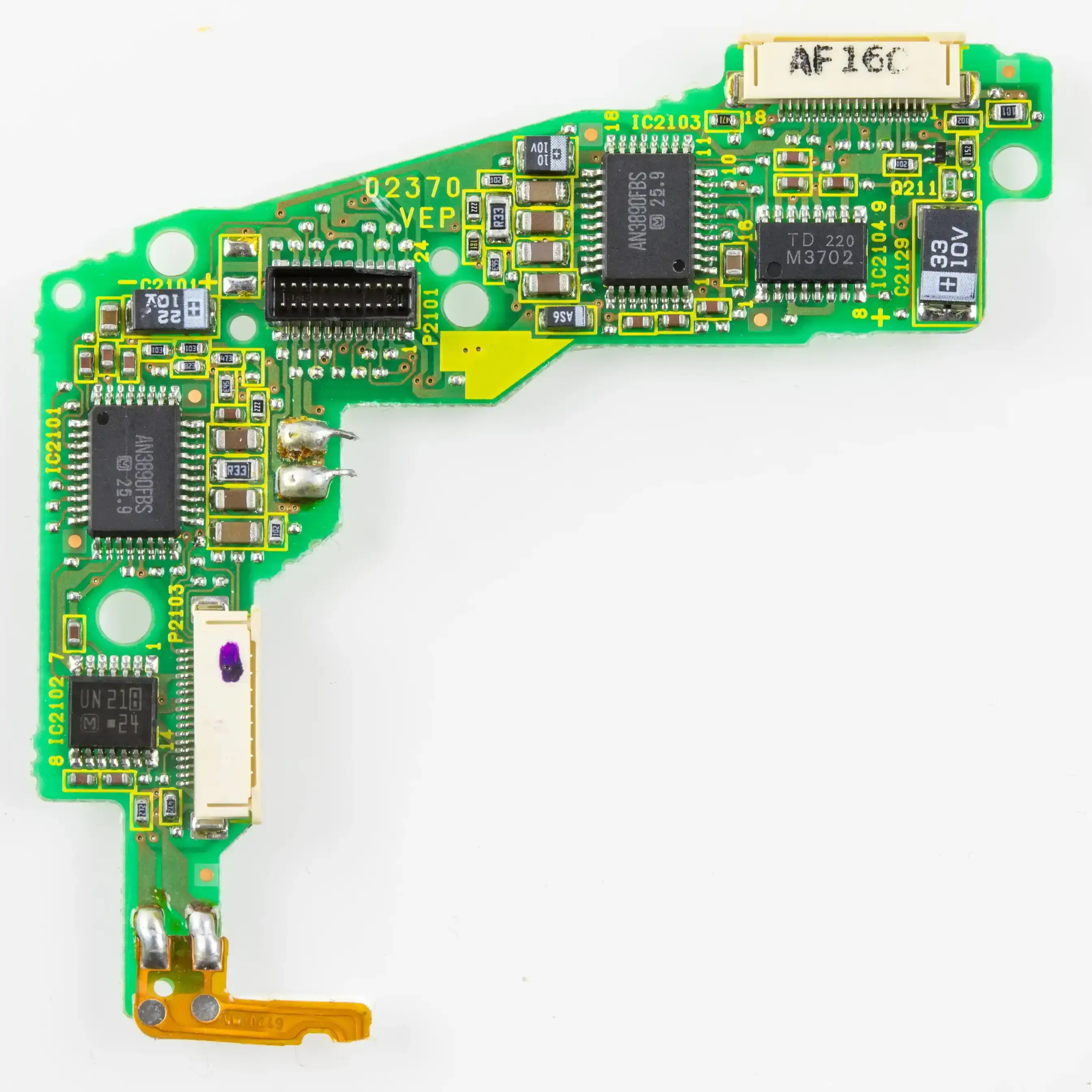
A motion controller PCB is the compact electronics platform that connects IMU sensing, user inputs, haptic feedback, battery power, and low-latency wireless communication inside a VR or AR controller. Its job is not only to route components; it must preserve tracking stability, RF performance, power integrity, mechanical fit, and repeatable assembly in a hand-held product that is constantly moving.
For VR/AR hardware teams, the most important release question is whether the controller board supports the system's latency, tracking, wireless, haptic, ergonomic, and production goals without treating the PCB alone as proof of motion-to-photon performance. The board can reduce avoidable latency and noise, but final interaction quality still depends on firmware, host processing, optical tracking, rendering, display timing, and end-product validation.
Key takeaways
- A motion controller PCB should be reviewed as a mixed-signal, RF, power, and mechanical-interface board, not as a simple input board.
- IMU placement, clock quality, analog/digital partitioning, and vibration isolation can affect sensor stability before the tracking algorithm ever runs.
- Bluetooth LE and many proprietary controller links operate in the 2.4 GHz band, so antenna placement, 50 Ω feed control, hand-blocking risk, and coexistence planning must be reviewed early.
- HDI, flex PCB, and rigid-flex PCB construction help fit sensors, triggers, joysticks, batteries, and haptic actuators into curved controller housings without excessive connectors.
- Haptic motors and RF transmit bursts can inject noise into power rails. A release review should check PDN impedance, grounding, decoupling, regulator location, and return paths.
- The strongest RFQ package includes enclosure constraints, IMU orientation, antenna location, battery data, flex bend zones, component height limits, and target test plan.
In this guide
- What is a motion controller PCB?
- Architecture of a VR/AR controller board
- How latency and sensor fusion shape PCB design
- 2.4 GHz wireless layout and antenna planning
- HDI, flex and rigid-flex for ergonomic controllers
- Power management, battery safety and haptics
- How controller PCBs interface with HMD and AR display systems
- Common failure modes in motion controller PCB projects
- Manufacturing and test controls before release
- Cost drivers and design tradeoffs
- RFQ checklist for a motion controller PCB
- Why work with HILPCB
- FAQ
What is a motion controller PCB?
A motion controller PCB is the board-level platform inside a VR or AR hand controller that reads motion sensors, captures buttons and triggers, drives haptic feedback, manages battery power, and communicates with the headset or host system. In more advanced controllers, the board may also support finger tracking, optical tracking markers, capacitive touch zones, or additional sensors for grip and gesture detection.
This is a different design problem from a generic remote-control PCB. A VR/AR controller is held, rotated, shaken, occluded by the user's hand, and exposed to repeated button, trigger, and haptic events. The PCB must therefore manage electrical performance and mechanical packaging at the same time.
The most common mistake is to treat the controller board as only a sensor carrier. In practice, the release review should ask five questions:
- Can the IMU and input signals reach the MCU with stable timing and low noise?
- Can the RF path maintain link quality when the user's hand covers part of the enclosure?
- Can the battery, charger, regulators, haptics, and RF bursts share power without corrupting sensors?
- Can HDI or flex construction fit the enclosure without overstressing copper or connectors?
- Can the production test plan verify motion, wireless, haptic, button, and charging functions repeatably?
A strong motion controller PCB answers those questions in the layout, stackup, connector plan, and test strategy before the first production build.
Architecture of a VR/AR controller board
A motion controller PCB usually combines sensing, computation, RF, power, haptics, and human-input circuits in a small enclosure. The exact architecture depends on whether the controller is a simple 3DoF accessory, a 6DoF tracked controller, a finger-tracking controller, or a professional training tool.
| Subsystem | Typical components | PCB design focus | Common release risk |
|---|---|---|---|
| Motion sensing | 6-axis or 9-axis IMU, optional magnetometer, optical tracking support | Clean power, fixed orientation, short sensor routing, thermal and vibration awareness | IMU noise, drift, or wrong orientation in production |
| Processing | MCU, application processor, sensor hub, flash memory | Clock integrity, boot access, firmware programming, high-speed interfaces | Debug access removed too early or noisy clock routing |
| Wireless link | Bluetooth LE, proprietary 2.4 GHz radio, antenna, matching network | 50 Ω RF feed, keepout, ground reference, enclosure and hand effects | Short range, packet loss, certification retest risk |
| User inputs | Triggers, buttons, joysticks, capacitive touch, grip sensors | Debounce strategy, ESD protection, flex routing, mechanical tolerance | Intermittent inputs after drop or repeated actuation |
| Haptics | LRA, ERM, voice-coil or other actuator driver | Current pulse handling, rail isolation, ground return control | Haptic pulses reset MCU or inject IMU noise |
| Battery and charging | Li-ion/Li-poly cell, fuel gauge, charger, protection IC, USB-C or pogo pins | PDN impedance, thermal area, charge path, ESD protection | Charging failures, rail droop, heat near battery |
| Manufacturing access | Test pads, programming header, RF test access, fixtures | Bed-of-nails access, panelization, keepout from tall parts | Prototype works but production test is slow or incomplete |
For compact products, HDI PCB construction can reduce routing congestion around MCUs, RF modules, sensors, and small connectors. When the enclosure curves around the user's hand, Flex PCB or rigid-flex construction can connect trigger modules, side buttons, LEDs, batteries, and haptic actuators without adding multiple board-to-board connectors.
How latency and sensor fusion shape PCB design
Motion tracking quality depends on the full system path: sensor sampling, MCU processing, wireless transfer, host tracking fusion, rendering, display scanout, and optical or inside-out tracking correction. The PCB is only one part of that path, so it should not be described as independently guaranteeing a motion-to-photon target.
A practical board review still matters because the PCB can create avoidable delay, jitter, or noise before the firmware begins. IMU traces that run beside a switching node, a weak ground return under the sensor, an unstable clock, or a noisy haptic event can degrade the data that sensor fusion depends on.
Many VR teams treat 20 ms or lower motion-to-photon latency as an aggressive system-level target for comfortable interaction, but that target must be decomposed across the whole product. The motion controller PCB mainly influences the front end of the chain: sensing, timing, power noise, RF link stability, and repeatable sensor assembly.
| Latency or tracking factor | PCB influence | Design review action |
|---|---|---|
| IMU sample stability | Sensor supply noise, clocking, ground reference, vibration coupling | Place IMU away from switching regulators, haptic drivers, and large heat sources; keep a clean local ground reference |
| Sensor-to-MCU path | I²C, SPI, interrupt routing, trace length, crosstalk | Keep routes short and avoid shared noisy return paths; use controlled routing where interfaces require it |
| RF packet reliability | Antenna location, matching, hand-blocking, coexistence with 2.4 GHz devices | Reserve antenna keepout, review enclosure materials, and preserve RF test access |
| Haptic event timing | Driver current pulses and rail droop | Separate high-current haptic returns from sensor and MCU reference paths |
| Firmware update and test | Programming and debug access | Preserve test pads or programming connectors until production test strategy is frozen |
| Mechanical repeatability | IMU orientation and flex strain | Define orientation marks, assembly datum, and rigid/flex bend limits in the drawing package |
The board-level goal is therefore not "zero latency." The goal is a stable electrical platform where the system team can tune tracking algorithms without chasing hardware-induced jitter, rail noise, RF dropouts, or assembly variation.
2.4 GHz wireless layout and antenna planning
Most VR/AR controller links use Bluetooth LE or proprietary 2.4 GHz radios. Bluetooth LE operates in the 2.4 GHz ISM band and uses 40 RF channels with 2 MHz spacing in the Bluetooth Core Specification. That creates familiar PCB concerns: antenna matching, RF feed geometry, ground reference, enclosure interaction, hand absorption, and coexistence with Wi-Fi or other 2.4 GHz devices.
For controller PCBs, antenna placement is often harder than the radio schematic. The user's hand can cover a large portion of the enclosure, and the controller may be rotated in every direction during use. A layout that works on an open bench can lose margin once installed in plastic, close to a battery, shield can, haptic motor, or metalized cosmetic part.
| RF design area | What to review | Why it matters |
|---|---|---|
| Antenna keepout | Clearance from copper, battery, screws, shields, metal coating and dense ground cuts | Nearby objects detune the antenna and reduce range |
| 50 Ω feed | Trace width, stackup dielectric, reference plane continuity, matching network location | Mismatch increases return loss and reduces useful transmit/receive power |
| Ground reference | Continuous return path under the RF feed where required by the antenna design | Broken reference planes make RF behavior less predictable |
| Matching components | Pi network or vendor-recommended matching close to the antenna feed | Allows tuning after enclosure and hand-effect measurements |
| RF test access | U.FL, coax pad, test point or fixture strategy depending on build stage | Enables conducted or fixture-based debug during EVT/DVT |
| Coexistence | Separation from clocks, DC-DC converters, USB, display links or other radios | Reduces self-interference and packet retries |
For a production design, the RF review should be tied to the real enclosure. Antenna simulation, vendor layout guidance, and conducted test access are useful, but over-the-air performance should be validated with the battery, housing, hand grip, strap, and nearby mechanical parts included.
If the board uses a certified RF module, the PCB still needs layout discipline. A certified module does not automatically make the final controller perform well or preserve all regulatory assumptions after antenna, ground, enclosure, and power changes.
HDI, flex and rigid-flex for ergonomic controllers
The ergonomic shape of a motion controller often conflicts with traditional rectangular PCB design. Sensors need fixed orientation, triggers need movement clearance, batteries need mechanical restraint, and buttons or grip sensors may sit on curved surfaces. This is why HDI, flex, and rigid-flex construction are common in VR/AR controller programs.
HDI PCB is useful when the main board has a dense MCU, memory, charger, RF module, IMU, button matrix, LED indicators, and connector fanout in a small area. Microvias and finer routing can reduce board area and make it easier to maintain clean ground and power planes.
Rigid-flex construction is useful when the design must connect multiple mechanical zones: trigger modules, top controls, side grip sensors, battery contacts, LEDs, and haptic actuators. Compared with multiple small rigid boards and cables, rigid-flex can reduce connector count, but it adds its own review burden.
| Packaging choice | Best fit | Board-level caution |
|---|---|---|
| Single rigid PCB | Simple controller shape, limited buttons, low routing density | May force awkward connector or antenna placement |
| Two or more rigid PCBs with cables | Clear mechanical separation between main board and input modules | More connectors and cable assembly variation |
| Flex PCB | Remote buttons, LED boards, trigger sensors, battery interconnects | Bend radius, copper grain direction and stiffener locations must be controlled |
| Rigid-flex PCB | Compact ergonomic controller with several fixed electronic zones | Higher fabrication cost and stronger need for early mechanical co-design |
| HDI rigid PCB | Dense MCU/RF/sensor area with small enclosure | Stackup, microvia reliability and test access must be planned early |
A flex or rigid-flex section should never be left as an afterthought. The release package should define bend radius, dynamic versus static bend areas, stiffeners, coverlay openings, connector reinforcement, and assembly sequence. If the flex crosses near a trigger hinge or a grip seam, mechanical fatigue can become the dominant reliability risk.
Power management, battery safety and haptics
Wireless motion controllers are power-constrained devices. The board must support active tracking, RF communication, haptic feedback, standby modes, charging, and sometimes firmware updates through USB or pogo-pin contacts. A poor power layout can show up as RF range loss, IMU noise, false button triggers, charging heat, or unexpected resets during strong haptic events.
The power tree should be reviewed by noise sensitivity, not only by voltage level. IMU and analog sensing rails usually need cleaner supply behavior than haptic drivers. RF power rails need local decoupling and short current loops. MCU core rails may tolerate switching converters, but the switch-node placement and return current path still matter.
| Load type | PCB concern | Practical design control |
|---|---|---|
| IMU and sensors | Low noise and stable reference | Use clean local regulation or filtering; avoid routing under switch nodes |
| MCU and memory | Fast current transients | Place bulk and high-frequency decoupling close to pins and preserve plane continuity |
| RF transmitter | Current bursts and return current | Keep RF rail decoupling tight and avoid shared high-impedance returns |
| Haptic actuator | High pulse current and back-EMF noise | Separate motor current loops; add filtering and driver protection as required |
| Battery charger | Thermal rise and ESD at charge port | Provide copper area, charge-path protection and mechanical port reinforcement |
| USB or pogo interface | ESD, alignment and wear | Use suitable protection and keep test/charging contacts mechanically supported |
Haptics deserve special attention because they are intentionally noisy mechanical and electrical loads. LRA and ERM drivers can draw pulsed current, create back-EMF, and mechanically shake nearby components. The PCB should keep the haptic current loop away from the IMU reference path and should avoid placing the IMU where actuator vibration is directly coupled through the board.
A good release review will ask whether the controller has been tested under the worst simultaneous case: RF transmission, high-rate sensor sampling, button input, haptic pulse, and battery near its lower operating voltage. That combination often exposes problems that static bench tests miss.
How controller PCBs interface with HMD and AR display systems
A motion controller PCB does not drive the display panel, but it does affect the perceived display experience because hand motion has to align with rendered motion. That is why the board should be discussed together with the HMD, AR display module, or host device at the system-interface level.
The original display-side topics—OLED versus Micro-LED, refresh rate, resolution and color gamut—are better treated as headset or display-board concerns. They should not dominate a motion controller article. For controller PCB release review, the useful display relationship is narrower:
| System element | Controller PCB relationship |
|---|---|
| HMD PCB or host processor | Receives controller data and fuses it with headset tracking and rendering |
| AR display PCB | Displays virtual content that must stay spatially aligned with controller input |
| VR headset PCB | Coordinates wireless link, tracking references, firmware updates and user input |
| Display refresh rate | Defines how quickly the system can present updated motion, but not by the controller PCB alone |
| Finger tracking module | May add more sensors, more flex routing, more MCU bandwidth and tighter test needs |
A strong board design helps preserve reliable input timing, but headset rendering, tracking cameras, display pipeline, operating system scheduling, and application code determine the final user-perceived latency. In public product copy, keep this boundary clear: the controller PCB supports a low-latency system architecture; it does not certify the entire VR/AR experience by itself.
Common failure modes in motion controller PCB projects
The following failure-mode table is a useful release-review asset because it connects symptoms to board-level causes. It helps engineering and sourcing teams focus on issues that are expensive to find late.
| Symptom in prototype or field test | Likely board-level contributor | Prevention during PCB review |
|---|---|---|
| Tracking jitter during vibration | IMU too close to haptic actuator or weak sensor grounding | Separate IMU from motor path and validate under active haptic events |
| Controller disconnects when gripped | Antenna detuned by hand, battery, shield or enclosure coating | Validate antenna with production-like enclosure and hand positions |
| MCU resets during strong haptic effects | Haptic current spike causes rail droop or ground bounce | Separate high-current loops and review PDN under transient load |
| False trigger or button events | Long unprotected traces, ESD exposure, flex strain or contact bounce | Add ESD strategy, debounce support and mechanical strain relief |
| Short battery life | Regulator inefficiency, leakage paths, poor sleep-state isolation | Review quiescent current, load switches and firmware-controlled rails |
| Charging port failures | Weak mechanical reinforcement or inadequate ESD protection | Add port anchoring, copper support, ESD device placement and test pads |
| RF range varies by build | Antenna matching changed by stackup, enclosure or solder variation | Keep RF matching access and define stackup/material controls |
| Flex cracks near hinge or grip seam | Bend radius too small or stiffener placed poorly | Define static/dynamic bend zones and assembly constraints |
| Production fixture cannot test all functions | Test pads hidden by housing, battery, tall parts or flex | Review test access before connector and enclosure freeze |
This table also explains why controller PCBs need early cooperation between electrical, mechanical, firmware and manufacturing teams. Many failures look like firmware bugs or user-experience problems, but the root cause can be antenna geometry, power rail droop, flex fatigue, or missing test access.
Manufacturing and test controls before release
Motion controller PCB manufacturing needs more than standard electrical continuity testing. The finished controller is a multi-domain product: RF, motion sensing, haptics, battery charging, user input, and mechanical fit all interact.
At the bare-board stage, the most important controls are stackup consistency, impedance where required, HDI microvia quality, solder mask registration, flex coverlay alignment, and dimensional fit. At the assembled-board stage, the focus shifts to component placement, IMU orientation, battery connector polarity, haptic driver function, RF performance and firmware programming.
| Build stage | Recommended checks | Why it matters |
|---|---|---|
| DFM review | Stackup, HDI rules, flex bend zones, component clearances, antenna keepout | Prevents layout features that cannot be built or assembled repeatably |
| Bare PCB fabrication | Electrical test, impedance coupon where required, microsection for HDI, dimensional inspection | Confirms physical board quality before components are added |
| SMT assembly | AOI, X-ray for hidden joints if needed, polarity check, reflow profile control | Reduces placement and soldering defects on dense boards |
| Firmware programming | Bootloader access, debug pads, unique ID or calibration data write | Supports production traceability and functional bring-up |
| Functional test | IMU response, button matrix, joystick, trigger, haptics, charging, standby current | Confirms user-facing functions, not only PCB continuity |
| RF test | Conducted or over-the-air fixture test depending on design stage | Screens antenna or radio assembly problems |
| Mechanical fit | Enclosure assembly, flex strain, trigger clearance, battery restraint | Prevents failures that only appear after final integration |
For teams planning Prototype Assembly, it is worth keeping extra debug access and RF tuning options in early builds. For Turnkey Assembly, the fixture strategy, programming files, BOM alternates, calibration procedure, and acceptance criteria should be part of the RFQ package.
Cost drivers and design tradeoffs
Motion controller PCB cost is driven less by board area alone and more by integration choices. A small HDI rigid-flex board can cost more than a larger conventional rigid board, but it may reduce connectors, simplify assembly, and improve enclosure fit. The right decision depends on product volume, reliability targets and mechanical constraints.
| Cost driver | What increases cost | When it is justified |
|---|---|---|
| HDI stackup | Microvias, sequential lamination, fine trace/space | Dense MCU/RF/sensor routing in a small controller body |
| Rigid-flex construction | Flex layers, coverlay, stiffeners, complex panelization | Curved ergonomics or reduced connector count |
| RF controls | Defined stackup, impedance control, antenna tuning access | Required for reliable wireless performance |
| Battery and charging safety | Protection ICs, ESD, thermal copper, port reinforcement | Needed for rechargeable handheld products |
| Haptics | Dedicated drivers, current handling, filtering and mechanical validation | Needed for premium interaction feedback |
| Production test | Fixtures, programming, calibration, RF and functional screening | Needed when build volume or return-cost risk increases |
| Enclosure-driven constraints | Component height limits, odd outline, multiple connector zones | Needed when ergonomics and industrial design are fixed |
The best cost optimization is not to remove controls blindly. It is to decide early which technologies are genuinely needed: conventional rigid, HDI rigid, flex interconnect, or full rigid-flex. A supplier review can often reduce cost by adjusting stackup, panelization, connector orientation or test strategy without weakening the user experience.
RFQ checklist for a motion controller PCB
A useful RFQ should let the PCB and assembly team understand the electrical design, mechanical constraints and test expectations at the same time.
Design files
- Gerber or ODB++ files
- NC drill files
- IPC-356 netlist if available
- Assembly drawings
- BOM with manufacturer part numbers and approved alternates
- Pick-and-place data
- Schematic PDF for engineering review
- Stackup requirement and impedance notes
- Flex or rigid-flex drawings if applicable
Controller-specific information
- Controller type: 3DoF, 6DoF, finger tracking, training controller or custom input device
- IMU orientation and placement constraints
- Antenna type, keepout and matching network information
- Battery type, voltage, capacity and charging interface
- Haptic actuator type: LRA, ERM, voice coil or other
- Button, trigger, joystick and touch-sensor interface requirements
- Enclosure material, wall thickness and nearby metal or coating information
- Flex bend radius, static/dynamic bend zones and stiffener locations
- Component height limits and ergonomic keepout areas
Testing and production requirements
- Functional test items: IMU, inputs, haptics, charging, sleep current, wake behavior
- RF test method: conducted, fixture-based, or over-the-air
- Firmware programming method and files
- Serial number or traceability requirements
- Environmental or drop-test expectations if applicable
- Prototype, EVT, DVT, PVT or mass-production stage
- Target quantity and delivery expectation
If the design is still uncertain, send the mechanical envelope and early stackup assumptions with the RFQ. For motion controllers, mechanical constraints often determine whether the correct answer is rigid PCB, HDI PCB, flex PCB or rigid-flex PCB.
Why work with HILPCB
HILPCB supports motion controller and VR/AR hardware teams from early board review through PCB fabrication and assembled prototype handoff. The most valuable support is often in the pre-release review stage, where stackup, antenna location, flex bend areas, component height and test access can still be adjusted before tooling and enclosure constraints become expensive.
Relevant HILPCB manufacturing routes include:
- HDI PCB for dense MCU, RF, sensor and connector fanout
- Flex PCB for curved input zones, trigger modules and compact interconnects
- High-Speed PCB for controlled digital interfaces and clean routing review
- High-Frequency PCB for RF layout discipline and material review
- Prototype Assembly for EVT/DVT builds and engineering validation
- Turnkey Assembly for component sourcing, SMT assembly, programming and functional test planning
Send your Gerber package, BOM, stackup notes, enclosure constraints and controller test plan to [email protected], or upload the files through the Quote page. For a controller project, the most useful early review usually focuses on antenna keepout, IMU placement, haptic current loops, flex bend zones, battery charging layout and production test access.
FAQ
What is the main purpose of a motion controller PCB?
A motion controller PCB connects motion sensing, user input, haptic feedback, battery power and wireless communication inside a VR or AR controller. It gives the system a stable hardware platform for tracking and interaction, but the final user experience also depends on firmware, host processing, tracking cameras and display timing.
Is a motion controller PCB responsible for the whole motion-to-photon delay?
No. The PCB affects sensor quality, timing, power noise and wireless reliability, but motion-to-photon delay is a system-level metric. Rendering, tracking algorithms, display refresh, operating system scheduling and application code also contribute.
Why is IMU placement so important?
The IMU is the controller's primary motion sensor. If it is placed near haptic vibration, switching-regulator noise, heat sources or mechanically flexible areas, the tracking algorithm may receive noisier data and require more correction.
Should a controller use Bluetooth LE or a proprietary 2.4 GHz link?
That depends on product architecture, latency goals, interoperability, power budget and host support. Bluetooth LE provides broad ecosystem support, while proprietary 2.4 GHz links may be selected for tighter control of timing or packet behavior. The PCB still needs antenna keepout, matching access and RF validation in either case.
When should I use HDI for a motion controller PCB?
Use HDI when the controller needs dense MCU, RF, sensor, charger and connector routing in a small board outline. HDI is most useful when it reduces routing congestion without eliminating test access or creating unnecessary microvia cost.
When is rigid-flex better than using small rigid boards and cables?
Rigid-flex is useful when multiple electronic zones must fit a curved enclosure and connector count is becoming a reliability or assembly problem. It should be chosen early because bend radius, stiffeners, stackup and assembly sequence must be designed together.
What should be tested on an assembled motion controller PCB?
A useful test plan should include IMU response, button and trigger function, joystick or touch sensing, haptic output, charging behavior, sleep current, firmware programming and RF communication. For production, RF and functional test fixtures should be planned before the enclosure is frozen.
What files should I send for a motion controller PCB quote?
Send Gerber or ODB++ data, drill files, BOM, pick-and-place files, assembly drawings, stackup requirements, schematic PDF, enclosure constraints, antenna information, battery and haptic specifications, flex bend requirements and your intended functional test plan.
Next steps
If your controller design is already constrained by enclosure shape, antenna location, IMU orientation, battery position or haptic feel, do not wait until production tooling to review the PCB. These constraints determine whether the board should be conventional rigid, HDI, flex or rigid-flex.
Upload your files through the Quote page or send the design package to [email protected]. HILPCB can review stackup, HDI feasibility, flex bend zones, RF keepout, power routing, haptic driver placement and test access before the next prototype build.