
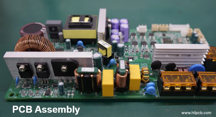
Reflow soldering is the predominant surface-mount technology (SMT) assembly process in which pre-applied solder paste is heated in a controlled thermal environment until the powder alloy liquefies, wets the PCB pads and component leads, and solidifies into robust metallurgical solder joints upon cooling. Rather than introducing molten solder from an external pot, the reflow process soldering methodology relies on precision stencil printing of solder paste directly onto surface-mount lands prior to automated component placement.
Understanding what reflow soldering is, how the soldering reflow process operates across its four distinct thermal zones, and when to specify reflow soldering vs wave soldering is vital for hardware engineers, NPI managers, and electronics buyers seeking high first-pass assembly yields and reliable field performance.
What Is Reflow Soldering? Meaning and Role in SMT Assembly
The core reflow meaning in electronics manufacturing describes a process where solder alloy—temporarily placed as a paste suspension of metal spheres and chemical flux vehicle—is heated to its liquidus state and "reflowed" into a cohesive metallic joint. When engineers ask what is reflow soldering or what does reflow mean, they are referring to this phase transition from granular paste to molten alloy and back to solid crystalline structure.
In high-volume electronics assembly, SMT reflow offers unmatched advantages over manual or wave soldering:
- Mass Concurrent Termination: A reflow oven simultaneously solders thousands of individual leads across dense multi-layer boards in a single continuous pass.
- Self-Alignment Phenomenon: The surface tension of molten solder naturally pulls misaligned surface-mount chips and quad-flat packages (QFPs) into alignment over their respective copper lands.
- Compatibility with Ultra-Fine Pitch: Reflow processes accommodate 0.4 mm pitch BGAs, 0201 and 01005 passives, and land grid arrays (LGAs) that wave soldering would bridge or destroy.
Whether described as pcb reflow, reflowing solder, or a solder reflow process, this thermal sequence forms the physical foundation of modern printed circuit board assemblies.
Reflow Soldering Process: The Four Thermal Stages
A continuous industrial reflow oven routes populated boards through multiple independently regulated heating zones to establish a precise thermal profile. The reflow soldering process is divided into four distinct functional stages:
Temperature (°C)
  ^
  |                     Peak (235-250°C)
  |                         /  |                        /  \  Reflow (TAL: 40-75s)
  |          Soak         /      |       (150-180°C)    /        |      +-------------+/          |     /                          \ Cooling
  |    /                               |   / Preheat                          |  / (1-3°C/s)                           0--+------------------------------------+---> Time (s)
1. Preheat Stage
The preheat zone raises the board temperature from ambient up to approximately 150°C at a controlled ramp rate of 1°C to 3°C per second. Controlled heating is critical: excessive ramp rates cause rapid solvent vaporization that spatters solder balls across the board, or induce thermal shock that cracks ceramic multilayer capacitors (MLCCs).
2. Thermal Soak Stage
During thermal soak (typically 150°C to 180°C for lead-free SAC305 alloys, lasting 60 to 120 seconds), heat equilibrates across the entire PCB assembly. This equalizes temperature between low-thermal-mass 0402 passives and massive copper ground planes or shielded IC packages. Simultaneously, chemical activators in the flux vehicle dissolve surface oxides on copper pads and component terminations while preventing re-oxidation.
3. Reflow Stage (Time Above Liquidus - TAL)
The reflow zone ramps the assembly above the alloy's melting point (liquidus temperature). For standard SAC305 solder (liquidus 217°C), the peak temperature reaches 235°C to 248°C. Molten alloy wets the metallic surfaces, dissolves base copper to form intermetallic compound (IMC) layers (primarily Cu₆Sn₅), and forms concave fillets. The duration above liquidus (TAL) is held between 40 and 75 seconds—long enough to ensure complete wetting without growing brittle intermetallic layers.
4. Cooling Stage
The cooling section solidifies the joints at a controlled rate (typically 2°C to 4°C per second). Fast, controlled cooling produces a fine, dense grain microstructure with superior mechanical shear strength and fatigue resistance, while avoiding the thermal stress associated with abrupt quenching.
For details on profiling instruments and thermocouple attachment, consult our reflow profile basics guide.
Reflow Soldering Temperatures: SnPb vs Lead-Free SAC305
The thermal window of a pcb reflow process depends fundamentally on the solder alloy metallurgy:
| Alloy System | Composition | Liquidus Temperature | Typical Peak Temperature | Time Above Liquidus (TAL) | Typical Application |
|---|---|---|---|---|---|
| Eutectic Leaded | Sn63Pb37 / Sn62Pb36Ag2 | 183°C | 210°C – 225°C | 45 – 75 s | Aerospace, military, mission-critical legacy |
| Standard Lead-Free | SAC305 (Sn96.5Ag3.0Cu0.5) | 217°C | 235°C – 248°C | 45 – 75 s | Global consumer, commercial, automotive (RoHS) |
| Low-Ag Lead-Free | SAC0307 (Sn99Ag0.3Cu0.7) | 217°C – 227°C | 240°C – 250°C | 50 – 80 s | Cost-sensitive high-volume electronics |
| Low-Temperature Lead-Free | Sn42Bi58 / SnBiAg | 138°C | 165°C – 180°C | 60 – 90 s | Heat-sensitive LEDs, flex-rigid displays |
Because lead-free reflow requires peak temperatures 25°C to 30°C higher than leaded systems, PCB laminates must provide adequate thermal endurance (high Tg and decomposition temperature Td), as detailed in our high-TG PCB guide.
Heating Methods: Convection vs IR vs Vapor Phase Reflow
Modern assembly facilities deploy three primary reflow heating technologies depending on board density and thermal mass:
- Forced Air Convection Reflow: The industry standard for volume production. High-velocity heated air or nitrogen gas circulates through discrete heating modules above and below the conveyor, delivering uniform thermal transfer regardless of component emissivity or color.
- Infrared (IR) Reflow: Historically popular, IR uses radiant quartz lamps. However, IR creates pronounced shadowing and component color sensitivity (black IC bodies overheat while shiny metallic shields reflect radiation), making it unsuitable for dense, modern assemblies.
- Vapor Phase Soldering (VPS): Utilizes the latent heat of condensing inert perfluoropolyether (PFPE) fluid vapor at a fixed boiling temperature (e.g., 230°C or 240°C). VPS guarantees that no surface can exceed the vapor boiling point, offering zero-shadowing and oxygen-free inert soldering for high-layer-count backplanes and aerospace electronics.
Reflow Soldering vs Wave Soldering: How to Choose for Your Board
Hardware teams evaluating wave soldering vs reflow (or flow soldering vs reflow soldering) must balance component types, packaging styles, thermal mass, and production economics:
| Comparison Dimension | Reflow Soldering | Wave Soldering |
|---|---|---|
| Primary Target Components | Surface-mount devices (SMD, BGA, QFN, passives) | Through-hole technology (THT, connectors, relays, electrolytic caps) |
| Solder Deposition Method | Precision stencil printing of solder paste before placement | Passing board over a continuous pumped wave of molten liquid solder |
| Double-Sided Board Assembly | Highly suitable (top and bottom reflow passes with paste) | Restricted; underside SMDs require epoxy glue and wave-tolerant footprints |
| Pitch Capability | Down to 0.3 mm pitch and 01005 passives | Generally limited to ≥1.27 mm pitch to avoid solder bridging |
| Thermal Shock to Board | Gradual, zoned heating (whole board heats up progressively) | Sharp localized thermal shock when bottom side hits liquid solder wave (260°C) |
| Dedicated Tooling Needs | Solder paste stencil | Wave solder carrier pallet / selective wave titanium aperture mask |
Process Decision Framework
- 100% Surface-Mount Boards: Choose 100% reflow soldering.
- Mixed Technology (Heavy SMT + Few THT Connectors): Perform SMT reflow for all surface-mount parts, followed by selective wave soldering or automated pin-in-paste (THR) reflow for the connectors.
- Heavy THT Boards (Power Supplies, Industrial Relays): Conventional wave soldering remains the fastest, most economical process.
Common Reflow Soldering Defects and Prevention
Maintaining tight process control prevents common SMT assembly failures:
- Tombstoning (Manhattan Effect): Small chip components stand on end during reflow. Cause: Unequal pad wetting forces caused by unbalanced copper heat sinking, asymmetric paste volume, or uneven component placement. Fix: Implement thermal relief on heavy copper pads and balance stencil aperture geometry.
- Solder Bridging: Molten solder connects adjacent pads, causing shorts. Cause: Stencil misalignment, excessive paste volume, or slumped paste during preheat. Fix: Optimize stencil aspect ratios and maintain ≥3 mil solder mask dams.
- Solder Beading and Spattering: Small solder balls form adjacent to passive chips. Cause: Rapid preheat vaporizing flux solvents violently, or paste squeezed under the chip body. Fix: Use home-plate or U-shaped stencil apertures to pull paste away from the component center.
- Solder Voiding: Gas pockets trapped within solder joints, particularly under large thermal pads and QFNs. Fix: Segment large stencil apertures into windowpane grids and optimize peak reflow dwell times.
Review our dedicated SMT assembly guide and BGA soldering defects analysis for defect mitigation strategies.
Frequently Asked Questions (FAQ)
What is reflow soldering?
Reflow soldering is an SMT process where solder paste applied to PCB pads is melted inside a heating oven, wetting metallic surfaces and forming solid electrical and mechanical joints upon cooling.
What are the four stages of the reflow soldering process?
The four stages are Preheat (gentle ramp-up), Thermal Soak (temperature equalization and flux activation), Reflow (heating above melting point to form joints), and Cooling (controlled solidification).
What temperature is used for reflow soldering?
For standard lead-free SAC305 alloy, peak reflow temperatures range between 235°C and 248°C, with a time above liquidus (217°C) of 40 to 75 seconds. Leaded Sn63Pb37 uses a peak of 210°C to 225°C.
Reflow vs wave soldering: which is better?
Neither is universally better; they serve distinct component types. Reflow soldering is superior for fine-pitch surface-mount devices (SMD, BGA, QFN). Wave soldering is ideal for through-hole connectors, power transformers, and heavy pin components.
What is the difference between convection and vapor phase reflow?
Convection reflow circulates heated air or nitrogen gas and represents the standard for high-volume manufacturing. Vapor phase reflow condenses a boiling inert fluid at a fixed boiling point, delivering perfect thermal uniformity across massive boards with zero overheating risk.
Turnkey PCBA Services with HILPCB
HILPCB provides comprehensive surface-mount assembly services backed by advanced multi-zone convection reflow ovens and stringent process controls:
- Precision Thermal Profiling: Multi-channel thermocouple profiling for every production batch.
- Ultra-Fine Pitch SMT Assembly: Full support for 01005 passives, 0.35 mm pitch micro-BGAs, and complex rigid-flex assemblies.
- 100% Inspection Coverage: High-magnification 3D AOI and 3D X-ray inspection (AXI) for BGA void verification.
Submit your BOM and Gerber data through our PCB assembly service or explore our turnkey assembly capabilities to accelerate your electronic hardware production.
Profiling thermal thermocouples across dense BGA centroids ensures robust solder joint formation even on small-batch prototyping pcb runs.