
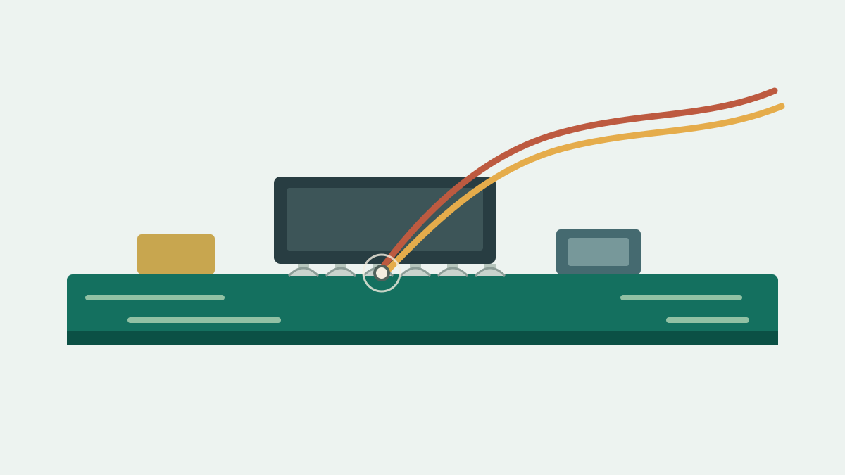
Choose a thermocouple attachment by first defining what temperature the profile must represent. Then place the effective measuring junction at that target, select an attachment compatible with the surface and process, and verify that it remains in place through the run.
High-temperature solder, thermally conductive adhesive and metal tape can all be useful, but each changes the local measurement conditions and has failure risks. No method is universally best. Consistent traces are valuable, but consistency alone does not establish that the junction accurately represents the intended solder joint or component.
For the wider process context, see reflow profile basics and reflow soldering. The measurement plan below focuses on where and how the temperature is observed.
Start with the measurement target
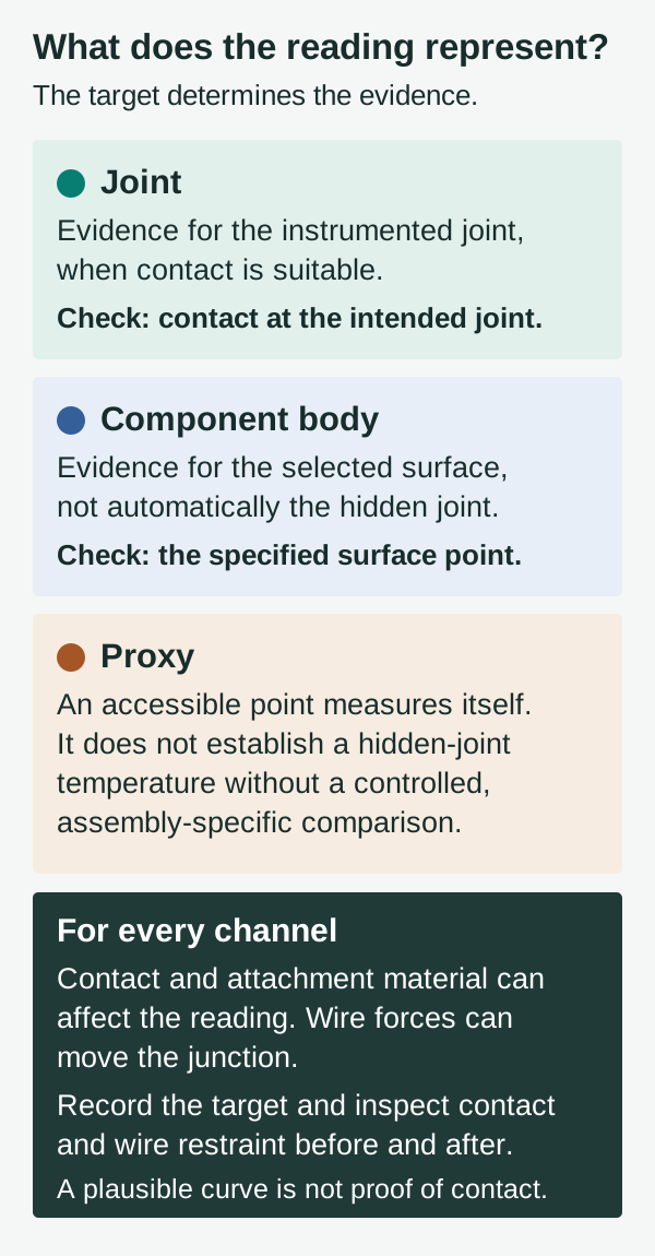
A thermocouple channel reports a temperature associated with its effective electrical junction. It does not automatically report the temperature of the nearest component, the board beneath it or an inaccessible solder joint.
These distinctions matter:
- Selected target: The feature the process decision concerns, such as an exposed solder joint, a component body or a board surface.
- Effective junction: The location in the thermocouple circuit responsible for the measurement. For a sound welded-tip assembly without unintended contacts, this is intended to be the tip.
- Local heat flow: Heat enters and leaves the junction through the target, attachment material, wires and surrounding environment. Added material can introduce thermal mass or shield the junction from airflow.
- Actual joint or component body: The physical feature whose temperature is of interest. It may differ in temperature from a nearby accessible point.
For a solder-joint decision, direct contact with the joint is preferable where practical and approved. A package-top reading or an opposite-side board reading may instead be a proxy for a hidden joint. Its relationship to that joint depends on the assembly and should be validated rather than assumed.
For temperature sensing during product operation, the related discussion of PCB temperature sensor placement and thermal-path validation considers how a sensor can track its intended air or component target.
Indium’s Attaching Thermocouples to a PCB for Reflow Profiling, Form 99842 R0, recommends direct joint contact for joint profiling and a populated board representative of the assembly. Its guidance is useful, but the final placement and attachment still depend on the product and measurement objective.
Select sites for the process decision
Use a representative populated profile assembly and select sites that investigate different thermal conditions. Candidates can include:
- A joint in a high-thermal-mass or densely populated region that may heat slowly.
- A joint in a low-mass or exposed region that may heat quickly.
- A temperature-sensitive component body.
- A product-specific concern, such as a hidden joint or a location near substantial copper or mechanical hardware.
These are hypotheses, not guaranteed hottest and coldest points. Component size, board position, airflow, copper distribution and neighboring parts can interact. Review the resulting curves and revise site choices when evidence points elsewhere.
The solder-paste process window and relevant component and assembly limits inform the process decision. They do not remove the need to establish that each channel is measuring the intended feature reliably.
Measurement-purpose matrix
The channel labels below are examples for planning, not a prescribed channel count.
| Purpose and example channel | Candidate target and placement | Attachment constraint and check | Important limitation |
|---|---|---|---|
| Joint in a potentially slow-heating area — J1 | Accessible joint near substantial thermal mass | Hold the junction against the joint without excessive attachment material; inspect contact before and after the run | A nearby pad or package surface is not automatically the joint temperature |
| Joint in a potentially fast-heating area — J2 | Accessible joint in a less-shielded, lower-mass area | Prevent wire drag from moving the small attachment; inspect the junction and feature after the run | The site is only a hot-location candidate until measured |
| Component temperature — B1 | Specified external area of a sensitive component body | Use a method compatible with the body and its surface; check for lifting or surface damage | An external body reading does not establish the internal die or hidden-joint temperature |
| Hidden-joint investigation — P1 | Approved direct access, or an accessible package or board proxy | Document whether placement is direct or indirect; verify attachment and any damage after the run | A proxy needs product-specific correlation; destructive access requires prior approval |
| Board-surface comparison — S1 | Defined board-surface location | Use enough clear area for stable contact without bridging nearby components; inspect for trapped air or lifting | The reading describes that surface location, not every joint around it |
Do not drill, remove a component or otherwise alter an assembly merely because a hidden site is desirable. Such work can damage conductors, the component or the joint and requires design knowledge and an approved procedure.
When investigating hidden BGA joints, retain the profile and thermocouple locations alongside other process evidence; see BGA soldering defects for defect investigation and inspection limitations.
Compare attachment methods at the actual site
High-temperature solder
A suitable high-temperature solder attachment can provide close contact and durable measurements. The attachment alloy must remain solid through the intended profile, and the amount applied should be controlled. Excess solder changes local thermal mass and can make the junction respond more slowly during heating and cooling.
The method also requires access and skill. Heat, flux, solder mixing or rework can alter the joint or damage the profile assembly. Material restrictions, exposure controls and contamination risks must be reviewed for the specific alloy and facility. Inspect for cracks and detachment after use; a soldered junction is not automatically permanent.
Indium’s application note prefers high-melting-temperature solder for its joint-measurement context. That is guidance for that context, not a requirement to solder every thermocouple.
Thermally conductive adhesive
A formulated thermally conductive adhesive can be an option when soldering is unsuitable. Evaluate the specific product, not just the word “epoxy”: surface compatibility, cure, bond thickness, thermal exposure, repeated-cycle behavior and removal all matter.
A bond that is too thick can affect response; one that is too thin or poorly cured may fracture. Adhesion to solder mask can differ from adhesion to metal. Also check electrical properties: an electrically conductive adhesive can create an unintended circuit or short if it contacts the wrong conductors or board features.
Metal tape
Aluminum tape can hold a junction against an accessible surface where there is enough clean, clear area. Its contact, retention, added mass and potential to shield the junction must be considered. A polyimide frame around the metal tape may help retain its edges; polyimide can also serve as wire strain relief away from the junction.
Inspect for air gaps and lifting. Do not bridge tape across components that could move when their production solder becomes liquid. Tape can be comparatively easy to remove in an open area but is not necessarily nondestructive on a dense assembly.
KIC’s Thermocouple Tactics: A Comparative Study of Attachment Methods compares attachment configurations using tested materials on bare and populated boards. Equipment and adhesive suppliers participated in the study. Its results apply to the materials and configurations tested: different attachment methods and layouts can produce different results. They do not establish a universal material ranking or replace a check at the actual attachment and layout.
Protect the junction and route the wires
Twisting insulated thermocouple leads for organization does not automatically create a short. The concern is damage or exposed wire: if bare dissimilar conductors contact each other before the intended junction, they can introduce an unintended junction or electrical path. That can change the effective measurement location or signal. The precise result depends on the electrical configuration; do not assume every contact produces the same error.
Inspect insulation, weld and leads before use. Keep bare conductors separated except at the intended junction, and prevent conductive attachment material from contacting them unintentionally. A continuity check alone does not prove correct placement: the intended thermocouple circuit itself is continuous.
Route and strain-relieve the wires so conveyor movement, snags or cable drag cannot pull the junction away. Avoid loading small features. Position the profiler and its thermal barrier according to their instructions so their mass and placement do not unnecessarily affect the assembly.
Check before and after every run
Before the run
The person preparing the measurement should:
- Confirm the board revision and populated state, measurement objective, target sites and channel map.
- Inspect each junction, insulation and connector; confirm the correct thermocouple and logger setup under the organization’s measurement controls.
- Check that each junction contacts its recorded target and that the attachment is intact, appropriately sized and compatible with the surface.
- Inspect wire routing, strain relief and clearances for snags, unintended electrical contact and possible interference with components.
- Confirm that the wires, attachment materials, profiler and barrier are suitable for the expected exposure and repeated use.
- Record the initial condition and any existing board damage.
Follow facility safety controls and equipment and material instructions for hot assemblies, moving conveyors, chemicals and soldering work.
After the run
After safe handling and cooling, inspect the same sites for lifting, cracks, displacement, damaged insulation, component movement and board damage. Review traces for discontinuities, unexpected separation or behavior inconsistent with the intended setup.
A plausible curve is not proof of good contact. Conversely, an unusual curve is a reason to investigate, not automatic proof that the process is wrong. Flag questionable channels, preserve their data and document the observation. If an attachment is repaired or moved, record the change and re-establish its suitability before using subsequent readings for the intended decision.
A hypothetical measurement comparison
The following invented example illustrates the difference between repeatability and agreement. It is not an acceptance limit, process limit or oven recipe.
Suppose method A is an established reference arrangement and method B is a candidate attachment. They are placed at adjacent, nominally similar locations on a representative assembly. Three illustrative runs produce these peak readings:
| Run | Method A peak | Method B peak | B minus A |
|---|---|---|---|
| 1 | 211 °C | 207 °C | −4 °C |
| 2 | 213 °C | 208 °C | −5 °C |
| 3 | 212 °C | 208 °C | −4 °C |
| Mean | 212.00 °C | 207.67 °C | −4.33 °C |
Method A’s observed range is 2 °C; method B’s is 1 °C. In this invented set, B has a smaller observed peak range, yet its mean is 4.33 °C lower than A’s. Three observations at adjacent sites do not isolate attachment repeatability from run-to-run or location variation.
That difference does not by itself establish B’s error or quantify either method's repeatability. Adjacent locations may have genuinely different temperatures, and method A is not automatically an exact reference. Investigate site differences, attachment mass, channel setup, calibration and measurement uncertainty. A suitable comparison might also examine the full heating and cooling curves, not just peaks.
Records, ownership and handoff
A profile record should make the measurement reproducible and its limitations visible. Capture:
- Assembly identifier, revision, populated state, target feature and direct-versus-proxy status.
- Channel map; thermocouple type and gauge; junction condition; relevant calibration and instrument identification.
- Attachment method, exact material or product, approximate amount, cure or preparation where applicable, and wire routing.
- Process setup used for the run, run identification, board use history, inspection results, damage and repairs.
- Trace files, comparison or uncertainty information, anomalies and disposition of questionable data.
Define ownership before profiling. A measurement planner or process engineer selects the objective and sites; a trained technician prepares, inspects and records the attachments; and the responsible process and quality personnel review the data against the applicable product and process requirements. The organization should designate who can approve repairs, proxy use and the final disposition.
Measurement handoff checklist
Before the receiving engineer uses the results, confirm that the handoff includes:
- The decision the profile is intended to support.
- Board identity, channel-to-target map and photographs or descriptions of junction placement.
- Attachment materials, pre-run and post-run condition, repairs and known damage.
- Identification of proxy readings and any supporting correlation evidence.
- Raw traces, instrument information and relevant measurement limitations.
- Unresolved anomalies, the responsible reviewer and the next required decision.
A profile-board reading informs process assessment; it is not, by itself, production qualification or proof that every production assembly meets its requirements. Qualification requires the applicable product, material, process and measurement evidence.
The profile record serves a different purpose from a PCB assembly inspection report; the latter can reference relevant supporting records when agreed for the project.
For an SMT assembly project, share the assembly revision, component and solder-paste requirements, and any temperature-sensitive locations. When requesting a quote, identify the measurement objective and any profiling or evidence requirements for review of the agreed scope.
FAQ
Does the thermocouple measure the solder joint or the component?
It measures at its effective junction. It represents a solder joint or component body only to the extent that placement and thermal coupling make it representative of that target.
Is high-temperature solder always the best attachment?
No. It can be durable, but access, added solder mass, damage risk and material controls may make another method more appropriate. Verify the chosen method at the actual site.
Can insulated thermocouple wires be twisted together?
Yes, twisting insulated leads is not automatically a short. Inspect for damaged insulation or exposed dissimilar conductors that could contact before the intended junction and change the measurement.
Can a package-top reading stand in for a hidden joint?
It can be used as a proxy if appropriate for the decision, but its offset from the hidden joint is assembly-dependent. Document the proxy and validate the relationship rather than assuming equivalence.
Do consistent repeated profiles prove accuracy?
No. Consistent traces show agreement in the observed setup, where several influences may vary. They do not independently quantify attachment-method repeatability, accuracy or representativeness. Those questions require appropriate comparison and evidence about the target, junction placement, attachment effects and instrument performance.