
Most Rogers PCB problems are decided long before fabrication starts. Choose a laminate with the wrong dielectric constant and your filter detunes. Feed the datasheet Dk into your impedance calculator instead of the design Dk and your 50Ω traces ship 6–8% off target. Pair a low-loss laminate with rough copper and you throw away half the material you paid a premium for.
This guide is written for the two people who usually share the decision: the RF/hardware engineer choosing and laying out the material, and the sourcing engineer who has to buy it, control cost, and qualify a supplier. It covers how to pick between RO4003C, RO4350B, and RT/duroid; the design rules that prevent re-spins; what a Rogers board actually costs versus FR4; and how we fabricate and test these boards at HILPCB, where we have shipped 50,000+ Rogers boards for wireless, aerospace, and automotive customers.
What Is a Rogers PCB — and Do You Actually Need One?
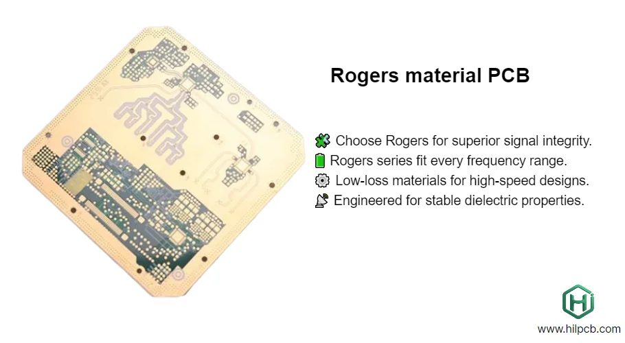
A Rogers PCB is a printed circuit board built on a high-frequency laminate from Rogers Corporation instead of standard epoxy-glass FR4. These materials deliver a stable, tightly controlled dielectric constant (Dk), a very low loss tangent (Df), and low moisture absorption, which together preserve signal integrity where FR4 falls apart.
The honest test for whether you need Rogers is loss and stability, not prestige. Two numbers make the decision concrete. On a 50Ω microstrip at 10 GHz, insertion loss runs roughly 0.8 dB/inch on FR4 versus about 0.2 dB/inch on RO4003C — nearly a 4× difference that compounds over trace length. FR4's Dk also drifts by roughly 200 ppm/°C and varies across a panel, which shifts impedance and phase; Rogers hydrocarbon-ceramic laminates hold Dk far more tightly across frequency and temperature.
Use this quick rule:
- Below ~1–2 GHz, mostly digital or low-power analog → FR4 or High-Tg FR4 is usually fine and far cheaper.
- Anything that transmits or receives RF energy — antennas, filters, power amplifiers, radar front-ends, 5G/mmWave, satellite links → Rogers (or a Rogers/FR4 hybrid) is usually the right call above a few GHz.
- Extreme thermal or power density → consider Rogers plus a ceramic substrate or metal-core layer for heat spreading.
If you are still unsure, the fastest way to settle it is to send us your operating frequency and loss budget — impedance and stack-up feedback is free with every quote.
RO4003C vs RO4350B vs RT/duroid: How to Choose the Right Rogers Material
Selecting a Rogers laminate comes down to four parameters, in this order: operating frequency, acceptable insertion loss, thermal/power environment, and cost. Work through them and the shortlist narrows to one or two materials fast. Our Rogers substrate selection guide adds RO5880 and application-by-application picks.
The table below uses published Rogers datasheet values so you can compare the materials engineers actually specify most often. Values are typical; exact figures depend on thickness and test method.
| Property | RO4003C | RO4350B | RT/duroid 5880 | Standard FR4 |
|---|---|---|---|---|
| Construction | Hydrocarbon-ceramic + woven glass | Hydrocarbon-ceramic + woven glass (flame-retardant) | PTFE + glass microfiber | Epoxy + woven glass |
| Dk (process, 10 GHz) | 3.38 ± 0.05 | 3.48 ± 0.05 | 2.20 ± 0.02 | ~4.3–4.6 (unstable) |
| Design Dk (for impedance) | ~3.55 | 3.66 | ~2.20 | varies widely |
| Df / loss tangent (10 GHz) | 0.0027 | 0.0037 | 0.0009 | ~0.02 |
| Insertion loss, 50Ω microstrip @10 GHz* | ~0.21 dB/in | ~0.25 dB/in | ~0.12 dB/in | ~0.8 dB/in |
| Glass transition (Tg) | >280°C | >280°C | PTFE (no Tg) | 130–180°C |
| Thermal conductivity | 0.71 W/m·K | 0.69 W/m·K | 0.20 W/m·K | ~0.3 W/m·K |
| Z-axis CTE | 46 ppm/°C | 32 ppm/°C | ~35 ppm/°C | 60–70 ppm/°C |
| UL 94 V-0 | No | Yes | No | Yes |
| Processing | FR4-compatible | FR4-compatible | Special (plasma, sodium etch) | Standard |
| Relative laminate cost | ~3–4× FR4 | ~3–5× FR4 | ~6–10× FR4 | 1× (baseline) |
*Insertion loss is geometry-dependent; treat these as order-of-magnitude comparisons, not spec values.
How to read the table for your design:
- Choose RO4350B for most commercial RF and 5G work. It hits the sweet spot: low loss, a low 32 ppm/°C Z-axis CTE for reliable plated through-holes, UL 94 V-0 (often mandatory for consumer/industrial products), and it processes on standard FR4 lines — no PTFE surcharge. It is the default for a reason.
- Choose RO4003C when you need tighter dielectric control and slightly lower loss, and flame retardancy is not a compliance requirement. Precision filters, phase-matched arrays, and narrow-band circuits benefit from its lower, tighter Dk.
- Choose RT/duroid 5880 (or RO3003) only when loss is critical and every fraction of a dB matters — mmWave, 77 GHz automotive radar, high-end space/defense. You pay for it in both material cost and fabrication: PTFE needs plasma treatment, sodium-etch, and conservative drilling. See our Teflon/PTFE PCB page for that process.
- Choose a hybrid (RF layers on Rogers, digital/power on FR4) when only part of the board is high-frequency. More on that below — it is the single biggest cost lever available to you.
One field-tested tip: talk to your fabricator before you finalize the material. We can confirm which thickness is in stock, which option is easier to source, and which fits your cost target — often saving one to two weeks of lead time.
Rogers PCB Design Guidelines That Prevent Costly Re-Spins
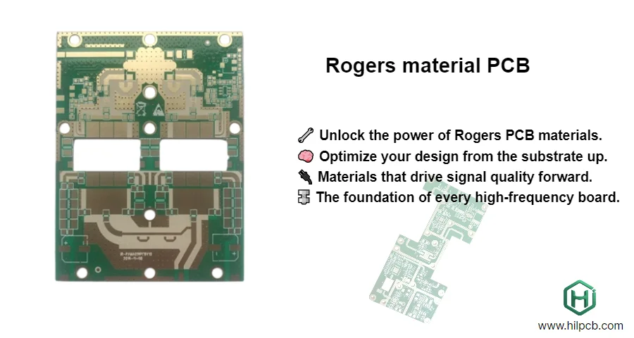
Rogers materials are unforgiving of layout assumptions carried over from FR4. These are the design rules and the specific mistakes we correct most often in DFM review — usually within 4 hours of receiving your Gerber files.
Use the design Dk, not the datasheet Dk, in your impedance calculator. This is the number-one error we see. Rogers publishes a process Dk (measured in a controlled stripline test — 3.48 for RO4350B) and a higher design Dk (3.66 for RO4350B) that accounts for copper roughness and real geometry. Enter 3.48 and your traces come out too narrow and your impedance ships high. Enter the design Dk. When in doubt, ask us for the measured process Dk of the specific lot we will use — if a fabricator can't give you one, that is a red flag.
Above ~5 GHz, copper roughness matters as much as the laminate. Conductor loss from rough copper can equal or exceed dielectric loss at high frequency. Specifying a low-Df laminate and then pairing it with cheap standard-ED foil wastes the material's advantage. For high-frequency RF, we recommend reverse-treated (RTF/LP2), rolled-annealed, or VLP foil, and we model it into the impedance calculation.
Set an achievable impedance tolerance. Customers routinely specify 50Ω ±3%, but the realistic manufacturing window is ±7% (±5% with our premium process). We test 100% of boards by TDR against dedicated coupons and typically hold 50Ω ±5Ω. Ask for tighter only where the circuit genuinely needs it; unnecessary tolerance drives cost and yield loss.
Respect Rogers-specific fabrication limits:
- Minimum feature size: 4mil/4mil standard, 3mil/3mil fine-line. Rogers etches differently than FR4.
- Via aspect ratio: keep to 12:1 or below for reliable plating; PTFE-based materials need even more conservative ratios due to drilling behavior.
- Layer registration: ±3mil standard, ±2mil for tight-tolerance HDI builds.
- Uniform copper weight per layer: mixing 0.5oz and 2oz on one layer causes plating problems. Split heavy copper into dedicated heavy copper PCB layers.
- Thermal relief: Rogers has different thermal behavior than FR4 — add thermal vias and copper pours, or integrate a high-thermal PCB layer for power stages.
Use our 3D viewer to check stack-up construction and mechanical fit before committing to fabrication.
Hybrid Rogers + FR4 Stackups: Cutting Cost Without Losing RF Performance
If only a few layers carry high-frequency signals, you do not need to build the whole board on Rogers. A hybrid stack-up places RO4003C or RO4350B on the RF layers and keeps digital, control, and power layers on FR4. Done correctly, this preserves RF performance where it matters and cuts material cost by 30–50%. It is the construction behind most production 5G, radar, and communications boards.
Three rules make a hybrid reliable:
- Match the CTE across the interface. The most common hybrid failure we see is mixing Rogers cores with an incompatible FR4 prepreg — the CTE mismatch microcracks via barrels after 3–5 reflow cycles. We select prepregs that bond cleanly to the Rogers core and match Z-axis expansion.
- Keep the stack symmetric. If a Rogers layer sits near the top, mirror it near the bottom. Asymmetric builds warp during lamination.
- Plan the impedance transitions. Signals crossing between a high-Dk and low-Dk region need managed transitions to avoid reflections; we model these in CAM before release.
We provide hybrid stack-up design consultation free with production quotes, and can combine Rogers with High-Tg FR4, ceramic, or metal-core layers in one balanced build.
Which Surface Finish Should You Use on a Rogers RF Board?
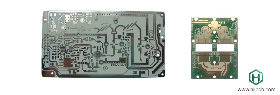
Surface finish choice has a real, measurable effect on RF performance, and the default HASL you might use on a consumer FR4 board is the wrong answer here.
- Immersion Silver (5–15 µin) — our top recommendation for high-frequency RF traces. It gives the lowest surface resistivity, minimizing skin-effect conductor loss, and keeps a flat surface.
- ENIG — highly reliable for assemblies with fine-pitch and BGA components; a strong all-round choice, with slightly higher loss than silver from the nickel layer.
- ENEPIG — preferred where passive intermodulation (PIM) is a concern, such as base-station and antenna work.
- Avoid HASL for RF. Its uneven surface topography degrades high-frequency performance and impedance control.
For medical, aerospace, or high-voltage designs we also offer hipot testing (250–500V DC typical) to screen the dielectric.
How Much Does a Rogers PCB Cost Compared to FR4?
There is no single multiplier, but two benchmarks set expectations. Raw RO4000-series laminate costs roughly 3–5× commodity FR4. At the finished-board level, depending on layer count, board size, and stack-up, total cost typically lands 5–20× an equivalent FR4 board — PTFE materials like RT/duroid sit at the top of that range.
The good news: most of that cost is controllable at the design stage. In order of impact:
- Material tier. Use RO4000-series instead of PTFE when performance allows — often a 50–60% material saving with no meaningful RF penalty below Ku-band.
- Hybrid construction. Rogers only on RF layers, FR4 elsewhere — 30–50% saving on a multilayer board.
- Panel utilization. A single board can waste 70% of a sheet. Arraying multiple boards and optimizing spacing typically recovers 20–40%.
- Standard thickness and copper. Using our in-stock RO4003C/RO4350B thicknesses and standard copper weights (0.5oz, 1oz, 2oz) avoids special-order surcharges and saves 1–2 weeks of lead time.
- Sensible tolerances and standard finishes. ENIG or Immersion Silver over exotic options; ±7% impedance unless the circuit needs tighter.
For production orders above 100 pieces, our engineers run a free cost-optimization analysis and quantify each of these levers for your specific design.
How HILPCB Manufactures and Tests Your Rogers PCB
Rogers fabrication is not FR4 with a different sheet loaded — it needs dedicated processing and 100% verification. Here is what happens to your board.
Material identity and traceability are project requirements. State the exact Rogers grade, dielectric thickness, copper foil, substitution rule, and required certificates in the RFQ. HILPCB confirms material availability, procurement lead time, incoming checks, lot records, and the documents that can ship with the board before accepting the order. These confirmations apply only to the quoted build and its supporting records.
Rogers-specific processing. Dedicated lamination profiles (different temperature/pressure than FR4), modified drilling parameters for PTFE-based materials, plasma treatment for plating adhesion, and etch chemistry tuned to the laminate.
100% impedance testing — non-negotiable. Every production panel carries test coupons (microstrip, stripline, differential pairs, via transitions) at no extra cost. We measure actual impedance by TDR up to 20 GHz (typical accuracy ±0.5Ω), plus 100% flying-probe continuity and isolation. Every shipment includes impedance data, a certificate of conformance, and the Rogers material certificate.
Certifications: ISO 9001:2015, IATF 16949 (automotive), IPC-A-600 Class 2/3, and UL listing; materials are RoHS compliant. Full material traceability is available for aerospace and medical work.
What to Send Us for a Fast, Accurate Rogers PCB Quote
To turn your quote around quickly and price it right the first time, include:
- Gerber RS-274X or ODB++ (or native Altium/Eagle/KiCad; IPC-2581 for full assembly data)
- Target impedance and frequency — we return calculated trace widths and a report within 24 hours, free
- Material and thickness (or tell us your loss/frequency budget and we'll recommend one)
- Layer count, copper weights, and surface finish
- Quantity and any certification/traceability requirements
We reply with a DFM review, impedance calculation, and stack-up recommendation. From prototype to production we scale from small-batch assembly to large-volume assembly and full box-build, typically at 50–60% lower unit cost at production volume.
Frequently Asked Questions — Rogers Material PCB
RO4003C vs RO4350B — which should I choose? Both are RO4000-series hydrocarbon-ceramic laminates with similar processing. Pick RO4350B for most commercial and 5G designs: it is UL 94 V-0 rated (often required), has a lower 32 ppm/°C Z-axis CTE for through-hole reliability, and is widely stocked. Pick RO4003C when you need tighter dielectric control and slightly lower loss and flame retardancy isn't a compliance requirement — for example precision filters and phase-matched arrays.
How is Rogers fabrication different from standard FR4? Rogers needs specialized lamination (different temperature/pressure), modified drilling for PTFE-based grades, plasma treatment for plating adhesion, and specific etch chemistry. RO4000-series processes on FR4-compatible lines; PTFE grades like RT/duroid require extra steps. We run dedicated Rogers processing and test 100% of boards.
Can you build multilayer and hybrid Rogers/FR4 stackups? Yes — we routinely build 4- to 12-layer Rogers boards and Rogers/FR4 hybrids. The keys are CTE matching between materials, correct prepreg selection, and symmetric construction to prevent warpage. Hybrid stack-up design consultation is free with a production quote.
How tight can you hold impedance? ±7% is standard and ±5% with our premium process. We verify 100% of boards by TDR on dedicated coupons (accuracy ~±0.5Ω) and provide the data with every shipment. Specifications tighter than ±5% are possible on select geometries — send the design and we'll confirm.
What surface finish is best for RF? Immersion Silver (5–15 µin) for the lowest conductor loss, ENIG for fine-pitch/BGA reliability, ENEPIG where PIM matters. Avoid HASL on RF boards — its rough surface degrades performance.
What is the minimum order and lead time? In-stock RO4003C/RO4350B ships with no material wait. Special-order laminates (RT/duroid, RO3003, RO6000) run 7–14 days from Rogers, typically 2–4 sheets minimum per thickness. We'll confirm exact lead time with your quote.
Do you support aerospace/automotive traceability and export-controlled work? Yes. Every Rogers batch carries lot traceability, and we provide material and impedance certificates with each shipment. We are IATF 16949 certified for automotive and support the documentation aerospace and medical programs require.
This article covers general material and manufacturing guidance. For datasheet specifications, always confirm current values with Rogers Corporation, and ask your fabricator for the measured process Dk of the specific lot used in your build.