
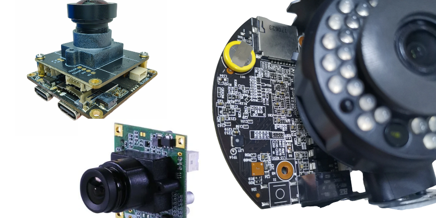
A security camera combines an image sensor, processing, power and communication interfaces with a lens and enclosure. The PCB must preserve the released electrical and mechanical design; image quality and analytics also depend on optics, exposure, firmware, scene and system configuration.
HILPCB offers high-speed fabrication, multilayer/HDI, SMT/THT and enclosure-integration routes for camera electronics. Specify the supplied sensor board, processor board, illumination/power board or complete assembly so the quotation covers the actual construction and tests.
High-Performance Surveillance Solutions: Ultra-HD Video Processing & AI Analytics
A 4K or 8K label does not define the sensor interface, raw-data rate, encoded bitrate, latency or image-quality requirement. Release the actual sensor/ISP/processor identities, output format, frame rate, channel mapping and firmware configuration.
Ultra-HD Video Processing
For a hypothetical 3,840 × 2,160 sensor output at 30 frames/s and 12 raw bits/pixel, active image payload is 3,840 × 2,160 × 30 × 12 = 2.986 Gbit/s. This excludes blanking, packet overhead and any packing/transport changes. It is not the Ethernet bitrate of a compressed stream. Use the selected sensor and interface specification to set the lane/clock, stackup and test requirements.
ISPs can provide noise reduction, stabilization or HDR processing when supported by the device and firmware. Pixel count alone does not establish low-light performance, depth measurement or usable detail. Dense sensor/processor packages may justify HDI fabrication; HILPCB lists 75/75 µm standard and 50/50 µm advanced trace/space on reviewed constructions.
Analytics and Edge Computing
HILPCB offers imaging-design consultation and integration support for 4K/8K and high-resolution applications, including designs with 100 MP sensor compatibility. Engineering can support custom AI/edge-processor hardware integration, thermal and RF design, and prototype through thousand-unit production, including customer approval-process support. Services span medical, automotive, industrial and defense imaging programs, and include high-frequency or radar-imaging options. Sensor compatibility and image performance depend on the selected sensor, optics, processor, software and qualified assembly.
Edge processors can run the customer's selected models locally, while other systems use a server or cloud service. Define model/runtime compatibility, memory, inference workload, power and update responsibilities. HILPCB's manufacturing service assembles the released electronics; analytics development and validation must be allocated in the project scope. See the smart camera board guide for the sensor/encoder/processor handoff.
Sensor, Processing and Application Inputs
- Sensor integration: Release the exact sensor/package, optics-related datums, supply/clock sequence and cleaning/handling restrictions. The digital camera PCB guide covers related interfaces; match package escape, output rate and assembly handling to the selected device.
- Processing acceleration: Match ISP, video encoder, VPU/GPU/NPU and memory bandwidth to the actual pipeline. Encoding and analytics have different quality, latency and storage tradeoffs.
- Low light and WDR: Define required lighting, exposure, motion and image-quality criteria. Multi-exposure WDR or noise reduction can introduce tradeoffs; neither guarantees recognizable detail in every scene.
- Behavioral and plate analytics: Specify the intended outputs, test scenes and acceptance/error measures for the approved application. A PCB build does not establish detection accuracy or authorize an automated response.
- Custom models: Retail, agricultural and industrial applications can use an appropriate processor platform, such as a selected EdgeTPU, Movidius or Jetson-based module when the released design supports it. Confirm exact module/software availability and thermals; these names are examples rather than interchangeable HILPCB products.
Fabrication and Assembly Choices
HILPCB's multilayer route lists standard 4–12 layers, reviewed constructions up to 64 layers and standard ±10% / advanced ±5% impedance options. The released interface targets, reference planes and coupon/test plan determine which route applies. SMT assembly adds package/stencil/reflow review, SPI/AOI, selected hidden-joint X-ray, programming and customer-defined testing. Define sensor cleanliness and mechanical/optical inspection alongside the electrical checks.
Night Vision and Infrared Illumination
Visible/near-IR cameras and thermal cameras use different sensing and optical systems. Axis's IR imaging overview distinguishes day/night filters and illumination from long-wave thermal sensing. Use the actual sensor and optical window requirements when releasing the enclosure.
IR LED arrays: Specify LED/driver current states, pulse or continuous operation, mounting and heat path. Illumination angle, reflections from the dome/window and exposure settings affect the image; correct LED placement alone does not prove a stated night range.
Thermal imaging: An uncooled thermal sensor detects emitted infrared radiation. Weather, target/background contrast and optical materials affect useful performance; it does not universally see through smoke or an ordinary glass window. Dual visible/thermal systems also need separate calibration and mechanical alignment.
Low-light or “starlight” imaging: Sensor sensitivity, lens aperture, exposure, gain and processing interact. Define the allowed motion blur and frame rate at the specified scene illumination rather than a generic marketing label.
Active IR control: Release the chosen LED wavelength, driver states, filter actuator and firmware control. Check visible glow, sensor response and image quality with the selected emitters, optics and exposure settings.
Adaptive illumination and motion: Brightness control can reduce saturation of nearby objects, but scene and optical validation are still required. Progressive scan does not eliminate exposure blur or every rolling-shutter effect. HILPCB's SMT assembly route can control the specified IR LED placement and thermal-interface assembly.
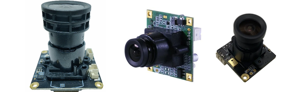
Network Connectivity, Security, and Durability for Surveillance Systems
Connectivity and power: Select Ethernet/PoE or a radio module from the installed network, data volume and power budget. The PoE powered-device circuit must match the selected supply/classification and cable conditions; include PTZ motors, heaters and IR illumination in peak as well as average load. TI's PoE overview separates powered-device and power-sourcing roles.
For an explicit power example, assume the camera loads require 14 W and the conversion stage is 90% efficient at that state. Required input to that stage is 14/0.90 = 15.56 W, before any additional cable/input losses or reserve. Compare that requirement with the actual negotiated/available power and startup behavior; it is not a generic PoE-class limit. Wi-Fi or cellular coverage and uplink capacity need installation evaluation rather than a guaranteed seamless link.
Security architecture: Secure boot, identities/certificates, authenticated updates and protected communications require the selected hardware, firmware and backend design. Release programming/provisioning roles, permitted credential handling and recovery tests. PCB layout and secure-element placement support that design but do not establish privacy compliance by themselves.
Outdoor durability: Specify temperature, condensation, coating, connectors, cable entries and thermal interfaces for the intended enclosure. IP67/IP68 concern evaluated enclosures or complete equipment. HILPCB's box-build route can integrate approved enclosure, harness and thermal parts with the ordered final test; define separate ingress or environmental verification where needed.
Maintenance: Identify the approved VMS/interface, firmware version, health reporting and update/recovery procedures. Include outage, reconnection and storage behavior in the equipment test plan. Remote diagnostics can support investigation without guaranteeing predictive maintenance or a particular service life.
Specialized Applications and Custom Solutions
The same electronics functions appear in different products, with different acceptance criteria:
Smart doorbells: Camera, two-way audio, event detection and network interfaces share a battery or wired supply. Define wake/record/transmit modes and receiver/app integration; the camera board alone is not a complete access-control system.
Traffic monitoring: Vehicle counting, scene analysis or plate-related applications need calibrated optics, exposure and an approved validation plan. Speed measurement or enforcement has additional system and authorization requirements; weather compensation does not guarantee accuracy in all conditions.
Retail analytics: People/queue counts and optional point-of-sale integration need application-specific data handling, model evaluation and access/retention rules. Do not infer privacy compliance from local processing or PCB manufacture.
Industrial monitoring: Release the relevant machine-vision or process-monitoring interfaces and environment. Hazardous-location use requires assessment under the applicable scheme; coating or a rugged board alone does not provide that approval.
Wildlife and environmental monitoring: Motion triggers and time-lapse can reduce some recording activity. Estimate battery life from usable capacity, capture/transmit duty cycle, standby, temperature and servicing needs instead of promising months of operation for every build. Select illumination and housing for the intended observation conditions.
Your Complete Surveillance Electronics Partner
HILPCB can connect fabrication, turnkey assembly, component sourcing and enclosure integration for the released camera design. Related medical, automotive, industrial and defense imaging boards have their own interface, qualification and inspection needs; see the broader camera PCB overview.
For a camera manufacturing quote, send fabrication/drill/stackup, BOM/CPL, sensor/processor identities, quantity and enclosure drawings. Mark optical datums, board-to-lens/sensor positions, contact/cleaning/coating restrictions, heat paths, antenna keep-outs and any illumination or PTZ power states.
For programmed or tested assemblies, include firmware, image/test targets, receiver/network setup, fixture connections, accepted output modes, limits and required records. Distinguish optical alignment/image-quality checks, board electrical/FCT and any separate environmental, RF or product-approval work. That lets the quotation price boards, sourcing, tooling, assembly and the evidence needed for the pilot build.
Frequently Asked Questions
What should a security-camera PCB prototype verify?
Use the pilot to evaluate the released sensor/processor interfaces, power modes, thermal path, package assembly, firmware and enclosure fit. Define optical/image-quality checks and radio/network tests where they are part of the supplied scope. Record the board/BOM/firmware revision, methods, limits and open issues before the next build.