
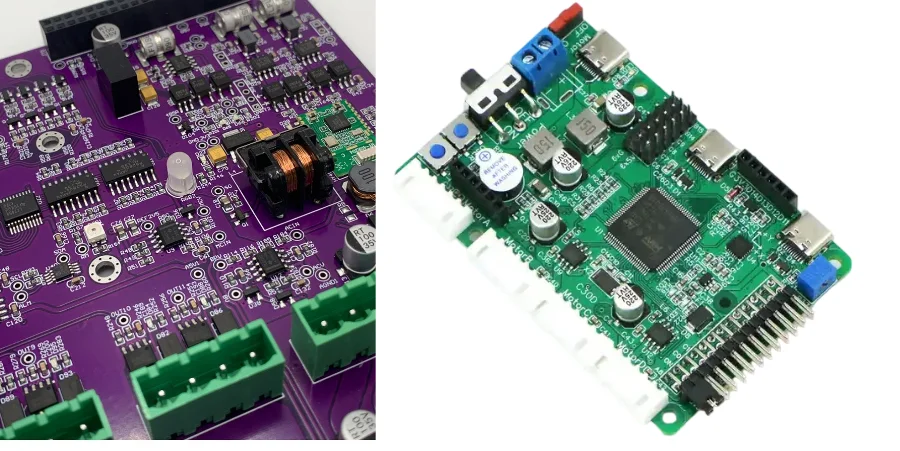
A warehouse robot PCB is the control, power, sensing, communication, and safety hardware platform that lets an AMR, AGV, robotic gripper, or logistics cobot move reliably inside an automated warehouse. It does not determine warehouse ROI by itself, but it strongly affects motion stability, communication uptime, battery efficiency, serviceability, and the quality evidence available before production release.
This guide focuses on board-level design and manufacturing review. It explains how to plan a warehouse robot PCB for motion control, industrial Ethernet, battery power, safety I/O, IIoT connectivity, environmental protection, PCBA testing, and RFQ handoff without turning system-level metrics such as MTBF, OEE, PL, SIL, or robot safety certification into unsupported PCB claims.
Key Takeaways
- Warehouse robot PCBs should be reviewed as multi-domain control boards, not as generic industrial PCBs. Motion, sensing, battery power, communication, and safety I/O all compete for space and noise margin.
- AMR and AGV electronics must separate high-current motor paths from encoder, IMU, LiDAR, camera, and safety-sensor interfaces.
- Industrial Ethernet, EtherCAT, PROFINET, RS-485, CAN, Wi-Fi, and 5G names describe interface context; they do not prove interoperability or conformance by themselves.
- Functional-safety standards such as ISO 3691-4, ISO 10218, ISO 13849-1, and IEC 61508 belong to the robot or safety-related control system, not to the bare PCB alone.
- A strong RFQ package should include not only Gerber files but also current loads, battery voltage range, safety I/O requirements, motor-driver thermal targets, communication interfaces, vibration environment, inspection requirements, and test plans.
In This Guide
- What a warehouse robot PCB actually does
- AMR, AGV, gripper, cobot, and inspection robot PCB routes
- Motion control layout and signal integrity
- Battery, motor-drive, and power integrity design
- Industrial Ethernet, wireless, and IIoT interfaces
- Safety I/O and functional-safety boundaries
- Reliability design for warehouse environments
- Manufacturing, inspection, and PCBA validation
- Common failure modes
- Cost drivers and RFQ checklist
- Why work with HILPCB
- FAQ
What a warehouse robot PCB actually does
A warehouse robot PCB usually sits inside a larger automation system. The same robot may need to drive traction motors, read wheel encoders, process IMU and LiDAR data, communicate with a warehouse control system, supervise battery health, monitor emergency-stop or safety scanner inputs, and survive vibration, dust, electrostatic discharge, and repeated charging cycles.
That is why the PCB must be reviewed as an interface and power platform, not only as a controller board. The central engineering question is not "Can the PCB run a robot?" The better question is:
Does the release package show how motion control, sensor acquisition, power conversion, communication, safety I/O, and service access are separated and validated on the board?
This framing avoids two common mistakes. The first is treating warehouse robotics as a software problem and leaving power noise, grounding, connector strain, and motor EMI until the prototype fails. The second is treating the PCB as if it can guarantee robot-level KPIs such as MTBF, OEE, MTTR, navigation accuracy, or safety performance level. A PCB can support those outcomes through good architecture and controlled manufacturing, but the final values depend on the complete robot system, firmware, mechanics, batteries, sensors, environment, and validation plan.
A practical warehouse robot PCB review should close these early questions:
| Review question | Board-level decision | Why it matters |
|---|---|---|
| What robot type is this for? | AMR, AGV, gripper module, cobot joint, inspection robot, charging controller, or communication module | Different robot subsystems need different routing, power, and test strategies |
| What current paths are high risk? | Motor drives, battery input, charging path, brake output, heater, lighting, or high-current I/O | High-current paths set copper weight, thermal layout, connector choice, and protection devices |
| Which signals are noise-sensitive? | Encoder, analog force sensor, IMU, camera clock, LiDAR trigger, safety input, RF antenna | These require zoning, shielding, clean references, and controlled return paths |
| Which interfaces leave the enclosure? | Ethernet, RS-485, CAN, USB, safety I/O, charging pins, antenna, debug, service connector | External ports drive ESD, surge, isolation, creepage, connector, and test-access planning |
| What must be tested at PCBA level? | Motor output, encoder input, communication port, safety loop, battery input, firmware programming, boot current | Test coverage should be designed before the layout is frozen |
AMR, AGV, gripper, cobot, and inspection robot PCB routes
The original phrase "warehouse robot PCB" can hide several different board routes. A better release review names the dominant robot subsystem first.
| Board route | Typical role | Key PCB burden | Avoid overclaiming |
|---|---|---|---|
| AMR main controller PCB | Sensor fusion, navigation compute, communication, safety I/O, power supervision | Mixed high-speed digital, low-noise sensor I/O, multiple ports, thermal management | Do not claim navigation accuracy without system validation |
| AGV drive-control PCB | Motor driver, encoder feedback, braking, battery interface | High current, high dI/dt, vibration, connector robustness, EMI containment | Do not claim vehicle safety certification from PCB layout alone |
| Robot gripper PCB | Force sensing, small motor/servo drive, end-effector I/O | Compact HDI/flex routing, low-noise analog sensing, cable strain relief | Do not reuse drive-board spacing rules blindly in dense end-effectors |
| Cobot safety/control PCB | Joint control, torque sensing, E-stop, safety I/O, redundant monitoring | Channel separation, watchdog, diagnostics, connector integrity, test access | Do not state PL/SIL compliance without complete SRP/CS assessment |
| Inspection robot PCB | Vision, LiDAR, ultrasonic, gas, thermal, or vibration sensing | Camera/USB/MIPI routing, RF, sensor shielding, field connectors, power filtering | Do not imply sensor accuracy without calibration and environmental testing |
| Robot communication PCB | Ethernet, CAN, RS-485, Wi-Fi, 5G, UWB, or gateway interface | Isolation, ESD, surge, antenna keepout, PHY layout, shield strategy | Do not claim EtherCAT/PROFINET conformance from hardware presence alone |
| Charging/BMS interface PCB | Docking contact, battery supervision, charge control, safety cutoff | High current, arc/ESD exposure, heat, creepage, connector wear | Do not claim battery safety approval at bare-board level |
This route separation matters because it keeps the PCB review tied to the actual subsystem. A traction-drive board, an AMR compute board, a gripper board, and a charging board may all belong to the same warehouse robot, but they do not carry the same PCB risk.
Motion control layout and signal integrity
Warehouse robots fail in subtle ways when motor power and feedback signals are treated as if they can share ordinary control-board layout rules. Traction motors, lift motors, brake outputs, relays, and switching converters create high dI/dt current loops. Encoders, Hall sensors, torque sensors, IMUs, safety scanner triggers, and differential communication pairs need clean timing and stable references.
A motion-control PCB should physically divide the board into power, control, feedback, and interface zones. The goal is not to create isolated islands everywhere. The goal is to make return-current paths predictable and to prevent motor switching noise from crossing the sensor and communication areas.
Motion-control design controls
| Area | Practical design control | Manufacturing or test check |
|---|---|---|
| Encoder input | Route differential pairs together, avoid return-plane splits, keep away from motor phase nodes | Continuity, impedance review when required, functional encoder test |
| Motor drive output | Use wide copper, short current loops, thermal via arrays, and proper gate-driver return paths | Copper thickness check, AOI, current-load functional test |
| Brake or relay output | Add flyback/transient control, reinforce connector and solder joints | AOI, ICT/FCT, mechanical inspection |
| IMU and analog sensing | Place away from inductors, motors, antennas, and thermal gradients | Noise-floor test, calibration support, power ripple check |
| High-speed camera or LiDAR interface | Control differential impedance, pair skew, connector launch, and ground continuity | TDR or coupon review where needed, interface bring-up test |
| Debug and service access | Keep programming and diagnostic access reachable after enclosure assembly | DFT review, programming fixture validation |
For high-speed digital links, High-Speed PCB methods such as controlled impedance, clean reference planes, careful via transition design, and connector-launch review may be needed. For dense processor or sensor boards, HDI PCB can reduce escape-routing pressure and shorten critical interconnects.
The biggest practical failure is not usually one wrong trace width. It is a board architecture that lets noisy power switching, cable transients, and sensor references overlap without a clear return-current plan.
Battery, motor-drive, and power integrity design
Power design is one of the highest-risk areas in AMR and AGV electronics. A warehouse robot often combines a battery input, charging or docking contacts, DC/DC converters, motor drivers, sensors, communication modules, brakes, lights, and safety circuits on one or more boards. The PCB has to carry current without excessive voltage drop, dissipate heat, and keep analog/digital subsystems from reacting to motor noise.
Power architecture review table
| Power domain | PCB concern | Recommended review question |
|---|---|---|
| Battery input | Surge, reverse polarity, connector heating, inrush current, fuse placement | Is the protection path close to the connector and sized for fault current? |
| Motor drive rail | High RMS current, switching loops, copper temperature rise, gate-driver noise | Are phase-current paths short, wide, and thermally supported? |
| Logic rail | MCU/SoC reset margin, watchdog stability, boot sequencing | Can the controller survive motor start/stop transients? |
| Sensor rail | ADC reference noise, analog front-end ripple, ground offset | Is the sensor supply filtered and routed away from high-current loops? |
| Communication rail | PHY reset, RF module current pulses, ESD event recovery | Are comms modules protected and decoupled near their load? |
| Safety rail | E-stop, safety input, redundant monitoring, power-loss behavior | Does power loss force a defined safe output state at system level? |
| Charging interface | Docking wear, arcing, hot-plug stress, temperature monitoring | Are contact geometry, protection devices, and thermal sensing planned together? |
For high-current motor or charging paths, Heavy Copper PCB can reduce resistive loss and temperature rise when the board design, copper thickness, stackup, and assembly process are planned together. For mixed control and power boards, a Multilayer PCB stackup with continuous power and ground planes usually gives better return-current control than a two-layer compromise.
Thermal design should be tied to the actual load case. Large copper pours, thermal vias, heat-spreader contact pads, and board-edge placement only help if the heat has a complete path to the chassis or airflow. A motor driver with an impressive copper area but no realistic path to the enclosure may still overheat during repeated acceleration cycles.
Industrial Ethernet, wireless, and IIoT interfaces
Modern warehouse robots rarely operate alone. They communicate with fleet managers, warehouse control systems, charging stations, safety systems, PLCs, and maintenance platforms. At PCB level, this creates a mix of wired industrial interfaces and wireless radios.
Interface options and PCB implications
| Interface | Common use in warehouse robots | PCB design focus |
|---|---|---|
| Ethernet / Industrial Ethernet | Docking stations, PLCs, robot gateway, maintenance port | 100 Ω differential routing, magnetics, ESD, connector shielding, clean PHY layout |
| EtherCAT / PROFINET context | Motion or automation network integration | Physical-layer layout and isolation; conformance remains device/system-level |
| CAN / CANopen context | Motor modules, BMS, distributed I/O | Bus protection, termination option, common-mode robustness, connector strategy |
| RS-485 / Modbus context | Industrial sensors, charging station, simple field devices | Isolation posture, TVS placement, termination/biasing, ground-reference control |
| Wi-Fi / Bluetooth | Robot maintenance, provisioning, local wireless data | Antenna keepout, 50 Ω feed, RF ground, coexistence with motors and DC/DC converters |
| 4G/5G module | Remote fleet connection, outdoor or distributed sites | RF layout, SIM/eSIM, power peak current, antenna separation |
| UWB or localization radio | Indoor positioning, ranging, tag integration | Antenna placement, RF clearance, clock stability, enclosure detuning |
Protocol names should stay at the right level. A board can be designed for an EtherCAT, PROFINET, CANopen, Modbus, OPC UA, or MQTT use case, but the PCB alone does not prove protocol conformance, deterministic timing, cybersecurity, or interoperability. Those require device firmware, stack implementation, integration testing, and often formal conformance processes.
What the PCB can do is make the physical layer defensible. That means clean differential routing, proper connector placement, robust ESD/surge protection, transformer or isolation-device layout where needed, antenna clearance for wireless modules, and test access for bring-up.
Safety I/O and functional-safety boundaries
Warehouse robots and collaborative robot systems operate near people, goods, racks, chargers, and other machines. Safety design is therefore a system-level requirement. The PCB may carry emergency-stop inputs, safety scanner interfaces, dual-channel inputs, brake control, watchdog monitoring, redundant output drivers, or safety relay/contactor interfaces, but a PCB does not receive a Performance Level or SIL by itself.
A safe article should use the correct boundary:
- The PCB supports safety-related control functions by providing separation, diagnostics, reliable connectors, watchdog circuits, protected I/O, and traceable manufacturing.
- The robot or safety-related control system is assessed against standards such as ISO 3691-4, ISO 10218, ISO 13849-1, and IEC 61508 depending on the machine type and application.
- PL, SIL, stopping distance, protective-field behavior, and collaboration safety require system risk assessment, firmware, sensors, actuators, diagnostics, validation, and documentation.
PCB controls that support safety-related functions
| Safety-related area | PCB contribution | Validation boundary |
|---|---|---|
| E-stop input | Dual-channel routing, connector robustness, filtering, diagnostics, test points | System must validate stop category, fault reaction, and safe state |
| Safety scanner interface | Protected I/O, stable power, communication integrity, shielding | Scanner coverage and protective field are system-level |
| Brake output | High-current driver, flyback protection, connector derating, thermal path | Brake torque and stopping distance are mechanical/system-level |
| Watchdog/supervisor | Independent reset or enable control, clean supply, test access | Fault reaction time is validated at system level |
| Redundant channels | Physical separation, independent routing, avoidance of common-cause shorts | PL/SIL requires architecture, MTTFd, DC, CCF, and validation |
| Safety relay/contactor interface | Through-hole strength, creepage/clearance posture, coil suppression | Final safety loop depends on selected components and wiring |
For AMR and AGV systems, ISO 3691-4 is often a key safety context for driverless industrial trucks and their systems. For industrial robots and cobot-style equipment, ISO 10218 and ISO 13849-1 are common safety-related contexts. IEC 61508 remains a general functional-safety foundation for electrical, electronic, and programmable electronic safety-related systems. These are important references, but they should not be used as one-line PCB compliance slogans.
Reliability design for warehouse environments
Warehouse electronics live in a practical, imperfect environment: dust, vibration, static discharge, battery switching, temperature changes, forklift traffic, charging contacts, maintenance handling, and mechanical shock. Reliability is therefore a combination of layout, material choice, assembly process, protection, and test coverage.
Environmental and reliability controls
| Risk | Board-level mitigation | Notes |
|---|---|---|
| Vibration and shock | Connector locking, underfill for selected components, strain relief, through-hole for high-force connectors | Validate with the robot's mechanical profile |
| Dust and moisture | Conformal coating where appropriate, sealed connectors, no-clean/cleaning process control | Coating must not block test points or heat paths unintentionally |
| Motor EMI | Short switching loops, snubbers/filters where needed, shielded cable strategy, ground continuity | Verify with system-level EMC testing |
| ESD at ports | TVS near entry point, chassis/shield strategy, short discharge path | Protection placement matters as much as part rating |
| Thermal cycling | High-Tg material where needed, copper balancing, via reliability review, derated components | Avoid treating Tg as a universal reliability cure |
| Connector wear | Reinforced pads, suitable plating/finish, mechanical support, insertion-cycle planning | Docking and charging contacts deserve separate review |
| Battery fault stress | Fuse/protection placement, clear fault current path, thermal sensing, isolation of logic | Battery safety belongs to the complete battery system |
High-Tg PCB can be useful when the operating temperature, reflow profile, or thermal cycling environment justifies it. Conformal coating or other protective treatments may be useful when moisture, dust, or corrosive exposure is expected. However, coating is not a substitute for correct creepage, connector sealing, cleaning, or enclosure design.
Manufacturing, inspection, and PCBA validation
A warehouse robot PCB is often judged by its prototype behavior, but production reliability depends on repeatable manufacturing evidence. The release package should include enough DFM, DFA, DFT, and functional-test planning to show that the board can be built, inspected, programmed, and serviced.
Recommended manufacturing and inspection flow
| Stage | What to check | Why it matters |
|---|---|---|
| DFM review | Trace/space, annular ring, copper balance, via design, solder mask, impedance notes | Prevents avoidable fabrication and assembly risk |
| DFA review | Component spacing, connector orientation, reflow/wave/selective solder constraints | Reduces assembly defects and rework |
| DFT review | Test points, programming access, boundary-scan/JTAG, fixture contact areas | Makes PCBA validation practical before enclosure build |
| PCB fabrication test | Electrical test, impedance coupons where required, visual and dimensional checks | Confirms bare-board integrity |
| SMT assembly | SPI, placement control, reflow profile, AOI | Controls solder defects at the source |
| X-ray inspection | BGA/QFN voids, bridges, head-in-pillow, hidden solder defects | Critical for processors, power modules, and dense packages |
| Through-hole/selective solder | Motor connectors, power terminals, relays, safety connectors | Improves mechanical strength where repeated stress is expected |
| Functional test | Boot, current draw, motor output, encoder input, communication, safety I/O, firmware | Confirms board-level behavior before robot integration |
| Environmental screen | Burn-in, temperature cycling, vibration, coating inspection when required | Should match the robot's risk profile |
For customers who need a complete build handoff, Turnkey Assembly can combine PCB fabrication, component sourcing, SMT, through-hole assembly, inspection, programming, and functional test under one coordinated PCBA package.
Common failure modes
A useful warehouse robot PCB review should explain what tends to fail and how to catch it before release.
| Failure mode | Likely board-level cause | Impact on robot | Prevention or detection |
|---|---|---|---|
| Encoder miscount or position drift | Motor noise coupled into feedback trace, poor shielding, wrong termination | Jitter, positioning error, unstable motion | Zoning, differential routing, filtering, functional motion I/O test |
| Random controller reset | DC/DC transient, PDN droop, poor decoupling, watchdog threshold mismatch | Robot stop, task interruption | PDN review, load-step test, brownout margin test |
| Communication dropout | PHY layout issue, ESD damage, cable shield problem, antenna detuning | Fleet disconnection or maintenance alarms | Port protection, impedance review, EMC pre-scan, link test |
| Motor driver overheating | Copper undersized, poor thermal via design, weak chassis heat path | Thermal throttling or shutdown | Thermal simulation, current-load test, IR imaging |
| Charging dock failure | Connector wear, arcing, insufficient protection, poor pad reinforcement | Charge interruption or contact damage | Docking-cycle review, contact temperature monitoring, reinforced layout |
| Safety input fault | Redundant channels routed too close, connector solder issue, poor diagnostics | False trips or unsafe fault masking | Channel separation, AOI/X-ray/THT inspection, safety I/O functional test |
| Corrosion or leakage | Residual flux, moisture, poor coating or enclosure protection | Intermittent faults, sensor drift, shorts | Cleaning control, ionic contamination checks if required, coating inspection |
| BGA solder fatigue | Vibration, thermal cycling, weak underfill decision, insufficient X-ray review | Processor or SoC intermittent failure | Package support review, X-ray, vibration/thermal profile validation |
Cost drivers and RFQ checklist
Warehouse robot PCB cost is not driven only by layer count. The real cost is shaped by current, heat, interface density, reliability evidence, inspection coverage, and assembly/test complexity.
Main cost drivers
| Cost driver | Why it increases cost | How to control it responsibly |
|---|---|---|
| Layer count and HDI | Dense SoCs, cameras, memory, RF, and safety I/O need more routing density | Separate compute, power, and I/O boards when modularity helps |
| Copper thickness | Motor and charging current require lower resistance and heat rise | Use heavy copper only where current and thermal analysis justify it |
| Controlled impedance | Ethernet, USB, MIPI, camera, and high-speed links need stackup control | Identify controlled nets clearly in the fabrication notes |
| BGA/QFN inspection | Hidden joints need X-ray and sometimes boundary-scan | Define which packages require inspection and acceptance criteria |
| Conformal coating | Adds masking, coating, curing, inspection, and possible rework limits | Use only where the environment and enclosure need it |
| Rugged connectors | Locking, high-current, or safety connectors cost more than simple headers | Match connector grade to vibration, current, and service life |
| Functional test fixture | Motor, encoder, communication, safety, and battery tests require fixtures | Plan test points and fixture strategy before layout freeze |
| Traceability | Serial number, process data, firmware version, and test record management | Apply to modules where field service and root cause analysis matter |
RFQ checklist for warehouse robot PCBs
Send the following data when requesting a quote or DFM review:
Design files
- Gerber, ODB++, or IPC-2581 files
- Drill files and fabrication notes
- Stackup target and controlled-impedance requirements
- Assembly drawings, centroid file, and BOM
- 3D model or enclosure constraints if connector fit matters
Electrical requirements
- Battery voltage range and maximum fault/current assumptions
- Motor phase current, peak current, and duty cycle
- Charging current and docking connector requirements
- Safety input/output list and required test access
- Communication interfaces: Ethernet, CAN, RS-485, USB, Wi-Fi, 5G, UWB, camera, LiDAR, or others
- RF antenna constraints and keepout zones if wireless is used
Environmental requirements
- Operating temperature range
- Vibration/shock profile or robot use case
- Dust, moisture, cleaning chemical, or coating requirements
- Expected service life and maintenance access assumptions
- Battery, charging, and docking-cycle conditions
Manufacturing and quality requirements
- IPC class expectation
- AOI, X-ray, ICT, FCT, burn-in, or environmental screen needs
- Programming and firmware-loading requirements
- Serial number and traceability requirements
- Prototype, pilot, and production quantity forecast
Why work with HILPCB
HILPCB supports warehouse robot developers with board fabrication and PCBA services for mixed-power, mixed-signal, and industrial communication electronics. The value is strongest when the project needs early DFM review, realistic stackup planning, assembly risk control, and functional test preparation before the pilot build.
Relevant HILPCB routes include:
- High-Speed PCB for controlled interfaces, processor boards, camera links, and industrial Ethernet layouts.
- HDI PCB for compact AMR compute boards, gripper modules, and dense sensor-controller assemblies.
- Heavy Copper PCB for motor-drive, charging, and high-current power paths.
- Multilayer PCB for clean power/ground planes and better return-current control.
- Turnkey Assembly for component sourcing, SMT, through-hole assembly, X-ray inspection, programming, and PCBA functional test.
For the first review, send your design files, load assumptions, connector plan, and test requirements to [email protected], or upload the package through the Quote page.
Reference standards and context
The following standards are useful as project context. They should be applied at system, equipment, or safety-function level as appropriate; this article does not claim that a bare PCB is certified to them.
- ISO 3691-4 — Industrial trucks, safety requirements and verification for driverless industrial trucks and their systems
- ISO 10218-1 — Robotics, safety requirements for industrial robots
- ISO 10218-2 — Robotics, safety requirements for industrial robot applications and robot cells
- ISO 13849-1 — Safety of machinery, safety-related parts of control systems
- IEC 61508 — Functional safety of electrical/electronic/programmable electronic safety-related systems
- IEC 61000-4-2 — Electrostatic discharge immunity test
- IEC 61000-4-4 — Electrical fast transient/burst immunity test
- IEC 61000-4-5 — Surge immunity test
- IPC-A-610 — Acceptability of electronic assemblies
- IPC-6012 — Qualification and performance specification for rigid printed boards
FAQ
What is a warehouse robot PCB?
A warehouse robot PCB is the electronic hardware platform used inside AMRs, AGVs, grippers, cobots, inspection robots, charging modules, or communication modules. It can host motion control, sensing, power conversion, battery supervision, industrial networking, safety I/O, and service diagnostics.
Is a warehouse robot PCB the same as an AMR PCB?
Not always. An AMR PCB usually refers to a board inside an autonomous mobile robot, while warehouse robot PCB is a broader term that can also include AGV drive boards, gripper control boards, cobot joint boards, charging dock boards, and robot communication modules.
Can a PCB alone guarantee MTBF or OEE?
No. The PCB can improve reliability through good layout, derating, thermal design, inspection, and test coverage, but MTBF and OEE depend on the complete robot system, software, mechanics, maintenance model, environment, and operating profile.
What is the biggest PCB risk in warehouse robots?
The most common risk is interaction between high-current motor power and noise-sensitive signals. Motor switching, battery transients, and cable ESD can disturb encoder inputs, sensors, communication PHYs, or controller power rails if the board is not zoned and protected correctly.
Does a robot PCB need heavy copper?
Only if the current, voltage drop, and temperature-rise analysis justify it. Heavy copper can help motor-drive and charging paths, but it also affects fabrication cost, etching, thermal balance, and assembly planning.
Can a warehouse robot PCB be certified to ISO 3691-4 or ISO 13849-1?
A PCB alone is not normally certified to those system-level safety standards. The PCB can support the safety-related control system with proper channel separation, diagnostics, reliable connectors, watchdog circuits, and traceable manufacturing, but final assessment belongs to the complete robot or safety function.
What should be included in a warehouse robot PCB RFQ?
Include Gerber or ODB++ files, stackup target, BOM, assembly files, current loads, battery voltage range, motor and charging requirements, communication interfaces, safety I/O, environmental conditions, inspection requirements, firmware/programming needs, and prototype or production quantities.
When should I use HDI or rigid-flex in a robot PCB?
Use HDI when dense processors, sensors, memory, or camera interfaces make ordinary routing impractical. Use flex or rigid-flex when sensors, buttons, grippers, or compact mechanical sections require reliable interconnect across moving or curved spaces.
Build the next warehouse robot PCB with a clearer release package
A warehouse robot PCB succeeds when the board architecture matches the robot's real risk profile: high-current motion, clean sensing, reliable communication, safe I/O, battery power, service access, and repeatable manufacturing. If those decisions are still scattered across mechanical, electrical, and firmware notes, the first build may expose avoidable problems too late.
Send your PCB files, current-load assumptions, interface list, and test requirements to [email protected], or submit them through the Quote page. HILPCB can review the layout, stackup, assembly plan, and inspection requirements before the design enters prototype or pilot production.