

High-speed HDMI hardware succeeds when signal integrity and manufacturing discipline are planned together. With controlled impedance, stable stackup execution, well-managed transitions, and connector-focused assembly, HDMI products can deliver consistent performance across different cables, sinks, and real-world environments—while remaining scalable from prototypes to volume production.
HDMI High Speed PCB Performance Planning
High-speed HDMI performance depends on the target bandwidth, routing length, and how many transitions the channel must pass through. The most efficient approach is to define build targets early, then align stackup, routing layers, and process capability to those targets.
At HILPCB, our engineers translate your performance goals into manufacturable build notes that reduce iteration and speed up validation.
Key Performance Planning Techniques
- Define target bandwidth and constraints: expected route length, port count, thickness limits, and key keepouts.
- Reserve a clean routing layer: keep high-speed lanes on planned layers with stable adjacent reference planes.
- Identify the critical transition zones: connector launch and layer changes dominate discontinuities.
- Lock the verification scope up front: decide whether impedance coupons and reporting are required for the build.
- Document requirements clearly: impedance target, tolerance expectation, and reference layer should be explicit in the RFQ.
Consistent Performance and Reliability
Clear manufacturing targets reduce trial-and-error and make first-pass bring-up and compliance preparation more predictable.
100Ω Controlled Impedance for HDMI High-Speed PCBs
100Ω differential impedance is the baseline for HDMI high-speed lanes, but true impedance control comes from geometry repeatability—dielectric thickness, copper plating, etch compensation, solder mask effects, and plane integrity.
At HILPCB, we prioritize stable impedance geometry and process repeatability, supported by high-speed PCB manufacturing when tighter control is needed.
Key Impedance Control Techniques
- Impedance-first stackup selection: choose dielectric and copper so 100Ω does not require extreme line/space.
- Finished copper awareness: include plating and final copper variation in the impedance model.
- Continuous reference planes: route over uninterrupted ground planes to stabilize impedance and return paths.
- Tolerance-centered design: avoid “edge-of-capability” geometry that drifts between lots.
- RFQ-ready build notes: specify impedance target, layers, and coupon requirement for accurate quoting.
Consistent Performance and Reliability
Manufacturable impedance reduces lot-to-lot drift and improves interoperability across different cables and displays.
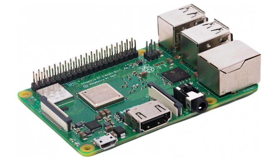
HDMI High Speed PCB Stackup and Materials
Stackup and materials affect insertion loss, skew sensitivity, assembly stability, and how consistently the board can be manufactured. Many projects start with FR-4, while longer channels or tighter margins may benefit from high-Tg or low-loss laminates.
At HILPCB, we match materials to channel needs and production goals—balancing performance and cost while keeping the build scalable.
Key Stackup & Material Techniques
- Start with stable FR-4 when margin allows: cost-effective builds using FR-4 PCB fabrication.
- Use high-Tg when assembly robustness matters: improve thermal stability with high-Tg PCB materials for connector-heavy or rework-prone products.
- Adopt low-loss where channels get longer: reduce attenuation and preserve eye margin for high-speed links.
- Increase plane control with multilayer structures: improve isolation and return paths via multilayer PCB manufacturing.
- Keep symmetry and plane discipline: stable lamination outcomes reduce skew and imbalance risk.
Consistent Performance and Reliability
A stable stackup improves yield, reduces respins, and supports smoother validation and production ramps.
Via Transitions and Stub Control
In high-speed HDMI channels, vias and layer transitions often dominate discontinuities. Managing stubs and maintaining clean return paths helps preserve margin and reduces sensitivity to cable variation.
At HILPCB, we apply a “transition hygiene” approach: minimize transitions, keep reference planes continuous, and use advanced processes when thickness or density demands it.
Key Via-Control Techniques
- Minimize layer changes: keep high-speed lanes on a planned layer when feasible.
- Return-path continuity: add ground stitching vias near signal transitions to keep current loops tight.
- Stub reduction strategy: control unused via barrel length when it impacts channel margin.
- HDI for dense breakout: improve routing freedom and transition quality with HDI PCB technology.
- Keep lane structures consistent: avoid lane-to-lane mismatch caused by inconsistent via geometry.
Consistent Performance and Reliability
Cleaner transitions reduce reflections and mode conversion, improving stability across different HDMI endpoints.
Connector Launch and Assembly for HDMI High Speed PCBs
The HDMI connector region is the most sensitive zone in many designs. A well-managed launch improves impedance continuity, while reliable assembly protects long-term durability in real use.
At HILPCB, we treat the connector as a controlled structure: launch geometry, grounding, and assembly process are planned together.
Key Connector Techniques
- Launch geometry consistency: keep pad/antipad and via fields stable and manufacturable.
- Shield and return-path discipline: maintain a low-impedance ground reference near the connector.
- Protection-friendly placement: reserve space for ESD/EMI components without forcing routing detours.
- Scale-ready assembly execution: ensure repeatability via SMT assembly services.
Consistent Performance and Reliability
Connector-first planning improves both signal stability and mechanical durability for products with repeated insertion cycles.
Verification for HDMI High Speed PCB Builds
Verification turns impedance control into measurable confidence. TDR coupons can confirm that the fabricated stackup and geometry match the intended impedance targets before a program scales.
At HILPCB, verification is designed into the build definition so measurements reflect real routing layers and real geometry.
Key Verification Techniques
- Define acceptance expectations: target impedance and tolerance window should be stated clearly.
- Coupon planning: ensure coupon structures match the real layer and trace geometry.
- Reporting scope: define whether each lot needs a report or sampling-based verification is sufficient.
- Use measurement to tune offsets: adjust geometry/stackup if systematic deviation is observed.
- Maintain repeatability: consistent process control reduces drift across production builds.
Consistent Performance and Reliability
For an end-to-end reference that connects impedance control, stackup execution, and production deliverables, see our HDMI PCB manufacturing guide.
Prototype-to-Volume Manufacturing for HDMI High Speed PCBs
High-speed HDMI programs move faster when fabrication, assembly, and supply chain execution are aligned early. A complete RFQ package reduces quoting cycles and prevents last-minute build changes that impact yield.
At HILPCB, we support rapid prototypes and stable production using the same core quality logic, then scale output as your program ramps.
Key RFQ & Scaling Techniques
- Provide complete PCB data: Gerber/ODB++/IPC-2581, stackup notes, thickness, copper weight, surface finish.
- Define performance targets: approximate channel length, number of ports, and any critical constraints.
- Call out special processes: multilayer needs, HDI requirements, stub control strategy, and inspection expectations.
- Plan the ramp path: validate early builds with small-batch assembly and scale with large-volume assembly.
- Choose single-vendor accountability if preferred: manage PCB + parts + PCBA through turnkey assembly services.
Consistent Performance and Reliability
A clear RFQ and staged ramp plan reduce iteration, stabilize yield, and accelerate the path from prototypes to production-ready HDMI hardware.
Common Questions
Why is 100 ohm differential impedance critical for HDMI high-speed PCB design?
Because HDMI high-speed lanes rely on controlled differential signaling to preserve eye margin and reduce reflections. If the finished impedance drifts too far from target, insertion loss, return loss, and interoperability problems become more likely.
When should an HDMI PCB use low-loss material instead of standard FR-4?
Standard FR-4 is often acceptable for shorter channels and moderate margins, but longer routes or tighter performance budgets may require low-loss laminates. The decision usually depends on total channel length, transition count, and compliance margin.
Why do via transitions matter so much on HDMI boards?
Each via transition can introduce impedance discontinuity and stub-related resonance that degrades high-speed signal quality. Backdrill, layer planning, and minimizing unnecessary transitions help protect channel performance.
What should be validated before volume production of an HDMI high-speed PCB?
Teams should validate stackup execution, impedance coupons, connector launch behavior, assembly quality, and first-pass signal performance. A staged prototype-to-volume plan reduces risk before full production ramp.