

HDMI ports are one of the most visible—and most performance-sensitive—interfaces in modern electronics. A well-executed HDMI port area supports stable link behavior, consistent EMI/ESD robustness, and long-term connector durability. While HILPCB does not manufacture HDMI ports/connectors, we manufacture the PCBs and assemble the PCBAs used in products that include HDMI ports, supporting prototype-to-volume builds with stable process control.
HDMI Ports and Connector Types
Different HDMI connector types come with different mechanical sizes, retention needs, and board-level constraints. Choosing the correct connector family early makes it easier to keep routing clean, grounding consistent, and footprints manufacturable.
At HILPCB, we support PCB fabrication and assembly for products that use various HDMI connector types, aligning footprint/keepout requirements with manufacturable PCB structures and assembly methods.
Key HDMI Port Selection Techniques
- Type A (Standard): common for TVs, set-top boxes, AV equipment, monitors, and industrial devices
- Type C (Mini) / Type D (Micro): compact consumer and portable products where space is limited
- Type E (Automotive): improved retention and ruggedization for vibration and harsh environments
- Multi-port planning: spacing, shell grounding, and mechanical reinforcement should be decided before routing
- Enclosure alignment: connector orientation and keepouts should match case geometry and cable insertion angle
Consistent Performance and Reliability
A connector choice made early helps the PCB stackup, grounding approach, and assembly plan stay consistent—reducing iteration later in the project.
PCB Stackup and 100Ω Planning Near HDMI Ports
For HDMI interfaces, stable performance starts with a stackup that supports manufacturable impedance geometry and consistent reference planes near the connector region. This is true whether the channel is short (cost-focused) or longer (margin-focused).
At HILPCB, we build HDMI-related PCBs with controlled geometry discipline using high-speed PCB manufacturing capability when tighter process repeatability is needed.
Key Stackup Techniques
- Impedance-first planning: select dielectric thickness/copper so 100Ω targets don’t require extreme line/space
- Plane continuity near the port: keep a solid reference plane adjacent to the HDMI routing layer
- Layer count choice by complexity: multi-port or dense systems often benefit from multilayer PCB builds
- Cost-effective baseline options: many programs start with FR-4 PCB manufacturing when channel margin allows
- Clear build notes: specify target impedance, routing layers, and any verification expectations in the RFQ
Consistent Performance and Reliability
A stackup built for manufacturability improves lot-to-lot consistency and makes product validation smoother—especially when scaling to production.
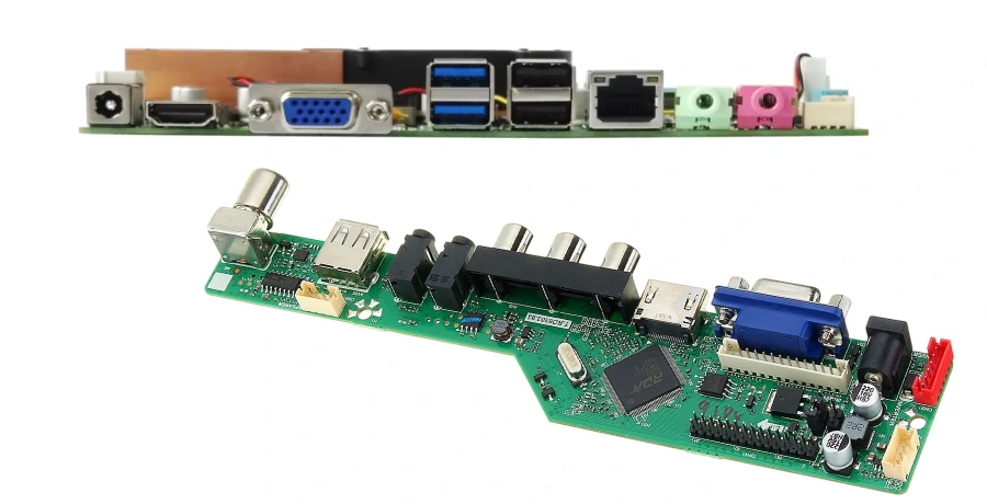
HDMI Connector Launch on the PCB
The connector launch area (pads, antipads, nearby vias, and immediate breakout) is where many designs win or lose margin. A launch that is consistent and manufacturable supports stable impedance continuity and repeatable assembly.
At HILPCB, we recommend connector-first floorplanning and manufacturable breakout structures; for dense escapes or tight constraints, HDI PCB fabrication can improve routing feasibility and transition quality.
Key Launch Techniques
- Connector-first placement: reserve space for launch geometry, ground stitching, and protection parts
- Short, symmetric breakout: keep the initial escape consistent to reduce discontinuities
- Manufacturable pad geometry: choose footprints that assemble reliably and remain consistent across builds
- Transition control mindset: reduce unnecessary discontinuities in the first centimeters after the connector
- Port-to-port consistency: keep launch structures uniform across multiple HDMI ports
Consistent Performance and Reliability
A clean launch improves channel stability and reduces sensitivity to cable or sink variation during validation.
Grounding and Shield Strategy for HDMI Ports
The HDMI port is a high-frequency interface; grounding decisions around the shell and return paths can influence both robustness and EMI performance. A consistent grounding strategy also makes assembly and inspection easier.
At HILPCB, we align grounding structures with your enclosure strategy and layer stackup; for products with stricter high-frequency constraints, high-frequency PCB materials may be considered based on system needs.
Key Grounding Techniques
- Continuous reference near the port: maintain a stable return path under the HDMI routing region
- Low-impedance shell grounding: implement a consistent shell-to-ground strategy aligned with enclosure design
- Ground stitching near transitions: reduce loop area and improve high-frequency behavior
- Avoid plane splits under HDMI pairs: keep return paths predictable
- Repeatable structures: choose grounding features that manufacture consistently across lots
Consistent Performance and Reliability
Disciplined grounding improves EMI readiness and helps HDMI behavior remain consistent across different installations.
ESD and EMI Protection Around HDMI Ports
Protection components work best when integrated as part of the port architecture. Placement and grounding quality matter as much as the component choice itself.
At HILPCB, we encourage port-area DFM review so TVS arrays and filters remain effective and manufacturable, without forcing late routing compromises.
Key Protection Techniques
- TVS close to the connector: minimize the length of unprotected routing
- Low-inductance ground return: multiple ground vias at TVS ground pads
- Symmetry for high-speed pairs: keep structures balanced to reduce mode conversion risk
- Filter placement discipline: keep footprints and transitions consistent with impedance planning
- Protection-zone routing control: avoid stubs and unnecessary branches near the port region
Consistent Performance and Reliability
Well-integrated protection improves robustness and supports stable HDMI operation in real-world handling environments.
HDMI Port Assembly on PCBs
Connector durability depends heavily on assembly execution. Many HDMI connectors include SMT pads plus mechanical anchors; a repeatable assembly flow improves long-term retention and stable electrical contact.
At HILPCB, we support connector-zone build consistency using SMT assembly and, where anchors are required, through-hole connector assembly processes.
Key Assembly Techniques
- Connector-zone process control: consistent soldering conditions for the port area
- Anchor joint integrity: ensure mechanical pins/tabs are soldered to support insertion cycles
- Inspection readiness: design for practical inspection of the connector region
- Scale-friendly methods: choose assembly steps that remain consistent from prototype to volume
- DFM feedback loop: adjust footprints/process notes early to improve yield
Consistent Performance and Reliability
Connector-focused assembly supports durable HDMI ports and stable yields as programs scale.
HDMI Ports RFQ Checklist for PCB Manufacturing and PCBA
A clear RFQ accelerates quoting and prevents build ambiguity. For HDMI port projects, the most important inputs are the connector definition, stackup expectations, protection constraints, and assembly scope.
At HILPCB, we recommend using a consistent RFQ package; for end-to-end HDMI build planning, you can reference our HDMI PCB manufacturing checklist.
Key RFQ Techniques
- PCB data: Gerber/ODB++/IPC-2581, thickness, copper, finish, and any controlled-impedance notes
- Connector definition: exact HDMI connector type/model, anchor requirements, and mechanical keepouts
- Protection requirements: TVS/filters and any placement constraints around the port
- Assembly files: BOM, pick&place, assembly drawing, and special instructions for the connector region
- Inspection/testing expectations: AOI baseline and any additional requirements as applicable
Consistent Performance and Reliability
A complete RFQ keeps fabrication and assembly aligned, supporting faster validation and smoother production scaling.
Common Questions
Why is the HDMI connector area often one of the most sensitive parts of the board?
Because it combines high-speed differential signaling, connector mechanical retention, ESD/EMI exposure, and repeated insertion wear in one small region. If that area is treated as only a footprint exercise, performance and durability issues often show up later.
What PCB details are most often overlooked around HDMI ports?
Connector launch continuity, shell grounding strategy, ESD placement, via usage, and impedance control right at the connector area are commonly overlooked. Many “connector problems” are actually board-level execution problems.
Why should the RFQ define fabrication and assembly expectations early for HDMI products?
Because HDMI interfaces are sensitive to connector selection, panelization, reinforcement, and assembly consistency. Locking those details early reduces the chance of mechanical drift or signal-performance variation in production.