
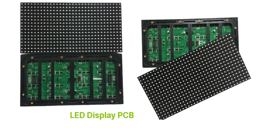
- A Mini LED backlight PCB should be reviewed as a dense power, thermal, and dimming-control system, not as a conventional LED strip board scaled up.
- The first engineering checks are dimming architecture, zone count strategy, thermal spreading path, driver placement, current distribution, and panel interface coordination.
- Mini LED performance depends on how the backlight PCB, LCD stack, driver electronics, and HDR target are matched as one system.
- Most failures come from uneven current distribution, trapped heat, weak local dimming control, connector bottlenecks, or unrealistic brightness targets that were never tied to a validation plan.
- Pilot success usually depends on freezing zone architecture, thermal path, assembly tolerances, and production test criteria before the first build.
Mini LED backlight uses a dense array of small inorganic LEDs behind an LCD stack to improve local dimming, brightness control, and HDR performance. The PCB challenge is to deliver stable current, controlled heat flow, predictable dimming behavior, and manufacturable routing at high channel density, not just to place more LEDs on the board.
Contents
- What to review first on a Mini LED backlight PCB
- Key design and validation rule table
- Early engineering trade-off table
- How dimming architecture affects routing and control
- How thermal design and HDR targets affect the board
- What prototype and assembly teams should freeze before release
- FAQ
- Next steps
- References
- Author and review
What to review first on a Mini LED backlight PCB
Mini LED is still an LCD-system architecture, so the PCB has to support both the electrical behavior of the backlight and the optical expectations of the display. AUO describes Mini LED as a backlighting unit that enables refined matrix local dimming and high brightness, while Innolux notes that active-matrix Mini LED control can drive each Mini LED element through TFT control. In practice, that means the board cannot be evaluated only by LED count. It has to be evaluated by dimming method, thermal path, current balance, and manufacturability.The first review points are usually:
- whether the product is using edge-lit, direct-lit, full-array local dimming, or active-matrix style control
- how the driver ICs, current paths, and connectors are distributed relative to the LED matrix
- whether the substrate and copper strategy can move heat away from dense LED zones
- whether the HDR target is tied to a real validation standard instead of vague "high brightness" language
- whether the LCD panel, diffuser stack, and backlight PCB are being reviewed together rather than as separate procurement items
For dense backlight control and heat-spreading layouts, it is usually worth checking metal-core PCB, high-thermal PCB, and high-speed PCB assumptions together before release.
Key design and validation rule table
| Rule / parameter | What to check first | Why it matters | How to verify | If ignored | | --- | --- | --- | --- | --- | | Dimming architecture | Confirm the actual local dimming method and zone control strategy | PCB routing, driver count, and thermal density all depend on architecture | System block review and optical-electrical requirements review | Overbuilt or underperforming design | | Current distribution | Review how LED strings or zones are fed and balanced | Uneven current creates brightness non-uniformity and thermal drift | Schematic review, current-path review, bench validation | Mura, hotspot risk, unstable zones | | Thermal path | Treat substrate, copper, vias, chassis contact, and enclosure airflow as one system | Mini LED density can create concentrated heat quickly | Thermal stack review and prototype measurement plan | Brightness drift, shortened life margin | | HDR target | Tie the product to a real target such as a DisplayHDR tier or customer-defined test plan | Brightness claims without a test path are not useful in engineering | Requirements review against VESA or product spec | Pilot confusion and failed acceptance | | Driver and connector placement | Freeze placement with mechanical and panel teams | Long current paths and weak interconnects increase loss and service risk | Layout review and first-article inspection | Voltage drop, rework difficulty, connector stress | | Production test path | Define how dimming, uniformity, and thermal behavior will be checked | A backlight board that powers on is not automatically production-ready | DFT review and pilot checklist | Hidden defects and subjective acceptance |Early engineering trade-off table
| Design choice | Usually stronger for | Main trade-off | What to confirm early | | --- | --- | --- | --- | | Conventional direct-lit LED backlight | Lower complexity and fewer control channels | Limited local dimming and weaker HDR behavior | Product cost target and image-quality target | | Mini LED local dimming backlight | Higher contrast control and stronger HDR potential | More channels, tighter routing, more thermal concentration | Zone plan, thermal path, driver architecture | | FR-4 backlight board | Lower cost and simpler fabrication in moderate-density designs | Weaker thermal spreading than metal-core options | LED density, brightness target, enclosure temperature | | Metal-core backlight board | Stronger thermal path for dense or bright backlights | Mechanical and electrical partitioning need more discipline | Insulation requirements, grounding, flatness | | Passive string control | Simpler channel management | Less granular dimming and less flexibility | Product image target and BOM constraints | | Active-matrix control | Finer control and more scalable local dimming | More complex driver and process strategy | Control IC ecosystem, manufacturing route |How dimming architecture affects routing and control
The dimming method should be locked before layout gets deep. AUO's public Mini LED materials focus on local dimming, high peak brightness, and HDR-oriented performance, while Innolux highlights active-matrix Mini LED control. Those are not interchangeable routing problems.Three layout decisions usually matter most.
1. Route for zones, not just for raw LED count
A board with many LEDs but weak zone control will not behave like a strong Mini LED backlight. The routing plan has to respect zone grouping, driver locality, current balance, and service access. For dense control regions, HDI PCB may be useful on controller-side boards even if the LED carrier itself uses a different substrate strategy.
2. Keep the driver-to-panel relationship explicit
The backlight PCB does not operate in isolation. If the LCD panel timing, diffuser stack, and local dimming algorithm are reviewed separately, teams often discover late mismatch between electrical control and visible image behavior. A Gerber viewer review is often useful for catching current-path and connector issues before fabrication.
3. Decide early whether the board is a thermal board, a control board, or both
Some Mini LED products split the control and carrier functions across multiple boards. Others integrate everything tightly. The right choice depends on thermal load, repair path, connector budget, and enclosure depth. Treating those as late-stage packaging choices usually creates rework.
How thermal design and HDR targets affect the board
Mini LED performance is often sold with broad marketing language, but engineering decisions should anchor to measurable requirements. VESA's DisplayHDR criteria define explicit luminance, black-level, and active-dimming expectations for different tiers. AUO's public Mini LED materials also tie the technology to HDR 1000 class behavior and local dimming performance. That does not mean every Mini LED board will achieve the same result. It means the PCB should be designed against a defined target, not a slogan.The most important checks are:
- whether the thermal stack can sustain the intended luminance target rather than only a short bench demonstration
- whether current density is creating local heating that shifts brightness or color behavior over time
- whether the mechanical stack provides repeatable contact, flatness, and heat removal under production tolerances
- whether pilot validation includes not just brightness but uniformity, dimming behavior, and thermal stability
If the backlight architecture combines dense LED mounting, driver assembly, and tight supply control, SMT assembly, turnkey assembly, and PCB prototype planning should usually be reviewed as one release package.
What prototype and assembly teams should freeze before release
Mini LED pilot risk goes down when the team freezes the actual control and thermal path before production hardware is ordered.A practical release checklist usually includes:
- Zone architecture approved
Freeze dimming zones, driver topology, and the relation between the backlight board and panel controller. - Substrate and thermal path approved
Decide whether FR-4, metal-core, or another thermal strategy is appropriate for the intended brightness and duty cycle. - Current-path review completed
Confirm copper width, feed points, and connector strategy for stable current delivery. - HDR and acceptance target defined
Tie validation to the intended customer or standards-based target instead of generic image-quality language. - Assembly and inspection path documented
Define placement tolerance, solder inspection, thermal material application, and optical or electrical acceptance checks. - BOM review completed
Use a BOM viewer review to catch LED binning, driver IC, connector, and thermal-interface-material risk before procurement.
If the design still needs fast iteration on heat and dimming behavior, quick-turn PCB support is usually useful before committing to larger builds.
FAQ
Is Mini LED just a normal LCD backlight with smaller LEDs?
No. The engineering difference is not only LED size. Mini LED designs usually involve denser local dimming control, tighter current distribution, stronger thermal demands, and stricter coordination with HDR and image-quality targets.
Why is thermal design so important on a Mini LED backlight PCB?
Because dense LED arrays can create local heat quickly. If the substrate, copper, vias, and chassis contact are not aligned, the board may show brightness non-uniformity, thermal drift, or shortened service margin.
Does every Mini LED design need a metal-core PCB?
No. It depends on density, brightness target, enclosure temperature, and thermal path. Some designs can stay on FR-4, while others need stronger heat spreading.
Should HDR targets be defined before prototype build?
Yes. Without a defined target, teams often confuse a bright demo with a production-ready backlight. Standards such as VESA DisplayHDR provide a clearer validation frame.
What is the first thing to freeze on a Mini LED design?
Usually the dimming architecture and thermal strategy, because they drive routing density, driver count, current distribution, and assembly assumptions.
Next steps
If you are developing a Mini LED backlight product, the most useful next step is usually to review the local dimming architecture, thermal path, and assembly method together before releasing the first pilot board.HILPCB can support that process through:
- Metal-core PCB and high-thermal PCB support when heat spreading is the main bottleneck
- High-speed PCB planning when controller-side signal quality also matters
- SMT assembly and turnkey assembly coordination for dense driver and LED builds
- PCB prototype and quick-turn PCB for early validation loops
- Gerber viewer and BOM viewer for layout and sourcing review
- Request a quote when your backlight architecture, thermal stack, and assembly package are ready