
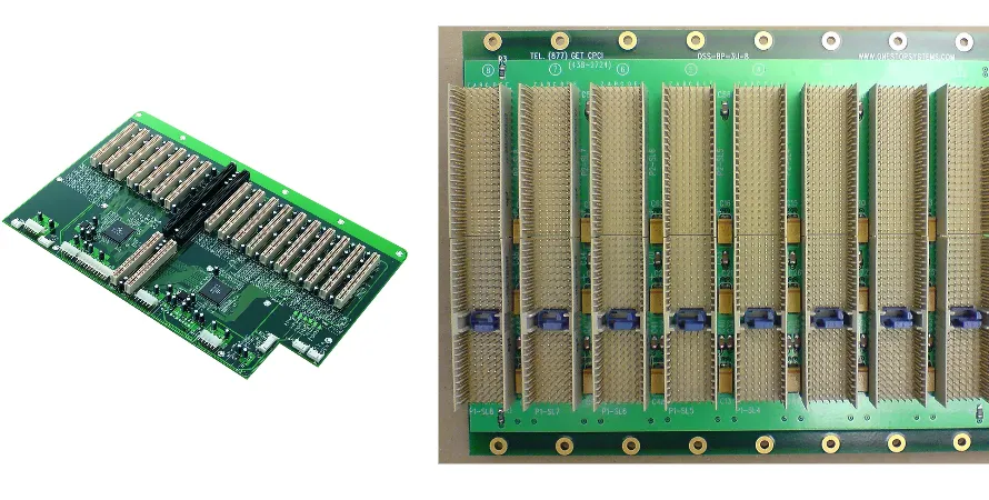
AI server backplane PCB stackup is one of the first decisions that determines whether a 112G or 224G interconnect system can actually ship. On large AI motherboards and rack backplanes, stackup planning affects insertion loss, reference continuity, IR drop, warpage risk, press-fit reliability, and final test coverage at the same time.
That is why teams should not treat stackup as a late documentation task. A stronger workflow links channel targets, laminate selection, copper weight, backdrill rules, connector escape, thermal paths, DFM review, and validation gates from the first prototype build. For AI platforms with PCIe 6.0, CXL, NVLink, and multi-kW power delivery, the stackup is the foundation that keeps performance, reliability, and manufacturability aligned.
Why AI Server Backplane PCB Stackup Matters
AI server backplanes usually have to solve several constraints in one board:
- High-speed channels must keep loss, skew, and reflection under control across long routes and multiple connector transitions.
- Power rails must carry very large current with low impedance and acceptable IR drop.
- Thick boards with 20+ layers and 4-6 mm thickness need symmetric construction to reduce warp and drill risk.
- Press-fit connectors, THT hardware, and large mechanical keep-out areas must still fit assembly and service requirements.
- Release decisions depend on measurable impedance, backdrill quality, electrical test access, and lot-level traceability.
For this reason, many teams evaluate AI server backplane PCB manufacturing capability together with high-speed PCB materials and impedance control, instead of treating stackup as a layout-only topic.
Key Reference Table for AI Server Backplane PCB Stackup
| Review item | Typical window | Why it matters |
|---|---|---|
| Channel material system | Mid-loss to ultra-low-loss laminate, VLP or HVLP copper | 112G/224G channels lose margin quickly if dielectric and copper roughness are not matched to route length |
| Differential impedance control | 85Ω, 90Ω, or 100Ω with ±5% or tighter target | Link training and eye margin collapse when stackup thickness and line geometry drift |
| Power and ground planes | Multiple continuous GND layers, 3 oz+ copper on critical rails where needed | Low-impedance PDN is required for multi-hundred-amp to kiloamp transient loads |
| Board thickness and symmetry | Often 20+ layers and 4-6 mm total thickness, with balanced build | Asymmetry increases warp, registration risk, and press-fit or assembly problems |
| Via stub control | Residual stub typically < 10 mil on critical nets | Backdrill quality directly affects resonance, return loss, and channel stability |
| Validation path | TDR, AOI or X-ray, flying probe, JTAG, FCT, and release records | Backplane quality cannot be judged by fabrication yield alone |
Exact targets still depend on channel length, connector model, current density, cooling method, and compliance class, but this table covers the minimum review set for most AI server backplane programs.
Low-Loss Materials and Impedance Windows for 112G/224G Channels
AI server backplane PCB stackup usually fails first in the channel, not in the schematic. Once signaling moves into PCIe 6.0, CXL, or 112G/224G-class links, dielectric loss, copper roughness, and reference discontinuity consume margin very quickly.
Typical review points include:
- Whether route length and connector count require low-loss, very-low-loss, or ultra-low-loss laminate instead of generic FR-4.
- Whether Dk and Df stability across temperature and frequency are good enough for the target data rate.
- Whether copper foil profile is controlled tightly enough to avoid extra insertion loss at high frequency.
- Whether impedance modeling matches real fabrication variables such as dielectric thickness, plating, and solder mask.
The material table below is not a substitute for full channel simulation, but it gives layout, SI, and sourcing teams a realistic starting window before laminate selection is frozen:
| Material grade | Typical materials | Df @ 10 GHz | Dk @ 10 GHz | Typical data rate |
|---|---|---|---|---|
| Standard loss | FR-4 (S1141) | ~0.020 | ~4.2 | < 5 Gbps |
| Mid loss | S7439 / FR408HR | ~0.010 | ~3.6 | 10-28 Gbps |
| Low loss | Megtron 4 / M4S | ~0.006 | ~3.4 | 28-56 Gbps |
| Ultra-low loss | Megtron 6 / M6G | ~0.002 | ~3.1 | 56-112 Gbps |
| Extremely-low loss | Megtron 7 / Tachyon 100G | < 0.0015 | ~3.0 | 112-224 Gbps+ |
That is why teams often pair stackup planning with high-speed backplane PCB design constraints, AI server motherboard routing strategy, and backdrill planning for thick high-speed stackups, instead of waiting until lab bring-up to debug channel loss.
Power Planes, Copper Weight, and Thermal Paths for Multi-kW Systems
Signal integrity is only half of the stackup problem. AI backplanes also have to distribute very large current into GPU trays, accelerator modules, memory power domains, and management rails. Poor plane planning creates IR drop, hot spots, and unstable load response even when routing looks clean.
A stronger power-focused stackup review usually checks:
- Whether power and ground layers are continuous enough to keep PDN impedance low over the relevant frequency range.
- Whether 3 oz or heavier copper is needed on critical current paths, bus bars, or connector entry regions.
- Whether plane pairing and dielectric spacing support both decoupling behavior and practical manufacturability.
- Whether thermal vias, copper spreaders, and heat flow paths are aligned with mechanical cooling architecture.
Thermal execution also belongs in the stackup review, not in a separate late mechanical discussion. On multi-kW AI platforms, material stability and heat spreading affect both electrical margin and assembly reliability.
- High-Tg materials with Tg >= 170 C are often required to reduce delamination, dimensional drift, and warpage risk under thermal stress.
- Dense thermal-via fields under VRM zones or other hot components should transfer heat into internal copper planes early, not after the prototype fails thermal test.
- For extreme local hot spots, copper coin, copper inlay, or other reinforced heat-spreading structures may need to be evaluated as part of the stackup release.
- Thermal simulation before the prototype build should confirm hot-spot location, temperature rise, and which stackup or copper changes actually reduce risk.
This is where heavy copper PCB capability for low-IR-drop power planes and server backplane design for data-center systems become part of the same engineering discussion, not separate handoffs between layout and manufacturing.
Backdrill, Connector Escape, and Press-Fit Assembly Risk
On AI server backplanes, the transition often matters more than the straight trace. Connector fields, via fields, and thick-board escape routing can introduce the worst return-loss and assembly problems if they are not constrained early.
A practical review should confirm:
- Whether critical via fields use backdrill or controlled stub length to prevent resonance on long plated-through holes.
- Whether anti-pad size, return vias, and reference continuity are maintained through connector launch regions.
- Whether press-fit connectors, THT brackets, and mechanical hardware leave enough keep-out for drilling, plating, and assembly tooling.
- Whether the board thickness and hole geometry still support reliable insertion force and barrel integrity.
This is why teams often align stackup sign-off with AI server backdrill planning, NVLink and high-density interconnect channel constraints, and turnkey assembly support for large AI server boards before pilot build.
DFM, Validation, and Release Control Before Volume Production
Even a strong stackup proposal still needs evidence from fabrication and test. Large AI backplanes are expensive to respin, so release control should be tied to measurable process outputs, not only simulation files.
Programs with fewer surprises usually require:
- Front-end DFM review for layer count, drill aspect ratio, symmetry, registration, and plating feasibility.
- TDR coupons and impedance records that confirm the real stackup matches the intended transmission-line model.
- AOI, X-ray, flying probe, or fixture-based coverage suited to the actual complexity of the board.
- Post-assembly checks such as SPI, AOI, and X-ray inspection for AI server backplanes and system-level release logic.
- Compliance and pilot planning linked with AI server motherboard compliance checks and quick-turn prototype learning cycles.
Before release to volume, teams should also confirm a few stackup-dependent manufacturing details:
- Whether thick, high-speed builds need multi-pass lamination and whether the press cycle controls interlayer bond quality and resin flow well enough.
- Whether deep-hole plating capability is strong enough for the required aspect ratio, so copper thickness remains reliable through long barrels.
- Whether ENIG, ENEPIG, or immersion silver is the better surface finish based on high-speed loss sensitivity, connector contact behavior, and multiple reflow cycles.
When stackup, fabrication, and validation are reviewed as one flow, teams catch risk earlier and avoid expensive late-stage redesign on large-format boards.
Common Questions About AI Server Backplane PCB Stackup
Common Questions
When does a backplane need ultra-low-loss material instead of standard FR-4?
Usually when channel length, connector count, and target speed push insertion loss beyond what mid-loss materials can support. PCIe 6.0, CXL, and 112G/224G links often force that decision early.
Is backdrill always required on AI server backplanes?
Not on every net, but it is often required on critical long vias where residual stubs would damage return loss or create resonance. The decision should be tied to channel modeling and actual drill depth capability.
How thick are AI server backplane boards in production?
Many projects land above 20 layers and around 4-6 mm total thickness, but the right answer depends on current demand, connector type, stiffness targets, and thermal strategy.
What usually breaks first in stackup execution?
Impedance drift, connector launch discontinuity, via stub control, warp, and PDN weakness are common failure points. Most of them are process issues that could have been caught before volume release.
Next Steps
If your AI server project needs stackup review for a large motherboard or backplane, request a manufacturing review or contact the HILPCB engineering team. HILPCB can help you confirm laminate selection, impedance targets, copper strategy, backdrill rules, and prototype-to-volume release gates before you lock the build package.