
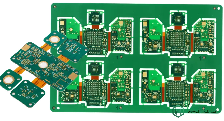
A rigid-flex PCB combines rigid component areas with flexible interconnections in one construction. The stackup, rigid-to-flex transitions, bend geometry and assembly handling must be designed together. Define whether the flex is bent only during installation or repeatedly during use before choosing materials and fabrication rules.
For HilPCB rigid-flex PCB manufacturing, submit the rigid and flex layer definition, material requirements, formed geometry and qualification plan. Confirm the fabrication and SMT assembly scope for the actual build rather than assuming every multilayer PCB feature is available in the flex region.
Why Choosing the Right Manufacturer for Rigid Flex PCB Production is Critical
Rigid flex PCB production requires advanced techniques and specialized equipment to meet the demands of modern electronics. As the technology integrates both rigid and flexible elements, ensuring high reliability across both sections is critical. Whether it’s for medical devices, automotive systems, or wearables, a reliable rigid flex PCB manufacturer can make the difference between success and failure in the field.
Key design and process reviews include:
- Lamination and process control for compatible bonding and registration; transition geometry must also manage mechanical strain
- Optimized material selection with adhesive and adhesiveless polyimide constructions to balance durability, performance, and cost based on your specific application
- High-density interconnect (HDI) options where package escape requires them, with qualified via geometry and build sequence
- Assembly tooling and fixturing where needed to support flexible areas and maintain placement/printing planarity
- Dedicated testing and validation such as continuity, application-specific bending validation and thermal-cycle testing when required by the approved qualification plan
- Comprehensive design support with DFM (Design for Manufacturability) reviews to optimize your design for reliability and cost-efficiency
Agree acceptance criteria and validation for the released construction. A DFM review can identify risks, but does not guarantee a particular flex lifetime or replace qualification in the assembled product.
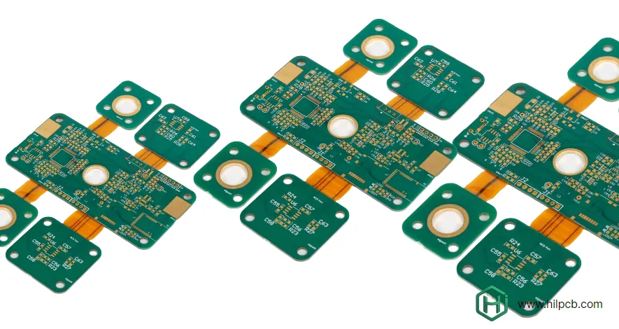
Rigid-Flex Fabrication Steps to Confirm
At HILPCB, we manufacture rigid flex PCBs for applications where reliability matters—from medical implantables to aerospace systems.
HILPCB provides integrated rigid-flex fabrication and assembly, including tooling, lamination, press-profile development and engineering support. Eligible constructions include up to 32 rigid layers and 0.1 mm microvias, with adhesive or adhesiveless material choices, free DFM/FEA assistance and 0201 assembly. Dynamic-flex life and −55°C to 125°C thermal testing are application-specific options; material and component traceability is available for the agreed scope. Quality systems include ISO 9001, ISO 13485, IATF 16949 and AS9100 at applicable certified sites and within their current scopes.
Identify the process owner, production sites and handoff controls for fabrication and assembly. Work across facilities can be controlled through released data, handling requirements, traceability and agreed acceptance; one building alone does not establish quality.
Review the proposed process for each section:
Rigid Section Fabrication Specify the required rigid-section layer count and via structure. HDI PCB processes can assist package escape, but the achievable microvia geometry, lamination sequence and rigid-flex combination require a build-specific capability review.
Flexible Circuit Production The flexible sections utilize rolled-annealed (RA) copper where cyclic bending calls for it; material choice is based on bend life, loss, construction and assembly constraints. Confirm the exact adhesive or adhesiveless polyimide grade, copper type and thickness, availability and approved substitutions.
Precision Lamination Lamination needs a qualified temperature, pressure and flow window for the specific cores, coverlays and bondplies. Review registration, resin fill at transitions, flex-window construction and any required process coupons. A generic polyimide designation does not establish the correct press cycle.
Quality Verification Validation should distinguish routine continuity testing from controlled-impedance coupons and bending qualification on an agreed sample plan; dynamic-cycle qualification must specify bend radius, cycle count and environmental conditions.
Rigid Flex PCB Design Support and Engineering Services
Rigid-flex failures can arise from design, fabrication, assembly or handling. Review the stackup and formed shape before tooling release so that the fabricator can identify process constraints and the product team can validate mechanical strain.
A DFM review should evaluate changes against the actual electrical, mechanical and qualification requirements. Reducing layers can lower some costs, but may change shielding, power distribution, flex thickness and strain. Compare a revised quotation and validation plan rather than assuming a fixed saving or reliability improvement.
A consumer electronics manufacturer submitted a 6-layer rigid flex design for a wearable device. Our engineering review identified that repositioning two components and adjusting the stack-up could reduce layer count to 4 layers—cutting per-unit cost from $18.50 to $11.80 while improving reliability. The design change took two days to implement but saved over $65,000 annually at their production volume. This recorded result is specific to that project and volume; it is not a promised saving or reliability outcome for a new order.
Design Review Includes:
- Stack-up optimization for your specific application requirements
- Transition-zone geometry, strain relief and any mechanical analysis needed for the application
- Bend radius, bend direction, bend count and installation tolerances, validated against the required life
- Material recommendations based on environmental conditions
- Component placement review identifying potential assembly issues
- Cost reduction strategies maintaining full functionality
You can preview your Gerber files using our Gerber viewer tool before submitting for quote, though design files for quotes and DFM analysis must be uploaded through our quote request page.
Rigid Flex PCB Assembly and Turnkey Manufacturing
For turnkey assembly, agree the fabrication, sourcing, assembly, programming and test scope. Define packing and handling between process steps so flexible areas are supported without creasing or exceeding their allowed bend geometry.
Specialized Handling Requirements Rigid-flex boards can use standard SMT processes with suitable support, tooling and profiles. Flexible regions may need carriers for printing and placement. Keep components and solder joints out of bending or transition areas unless the design and process explicitly support them.
Reflow profiling for rigid flex boards requires careful attention to thermal gradients. The different thermal masses of rigid and flexible sections can create temperature variations during reflow. Verify the assembly profile against component, laminate, adhesive and moisture-handling requirements, with measurements at the relevant rigid and flexible areas.
Assembly Scope to Request
- Component sourcing and procurement management
- Custom tooling and fixturing for rigid flex geometries
- SMT assembly with component sizes and placement limits confirmed for the build
- Through hole assembly when required
- Conformal coating and environmental protection
- Final functional testing and inspection
If box build assembly is required, supply the enclosure, harness, mounting and formed-flex drawings and agree the complete-device inspection and functional-test responsibilities.
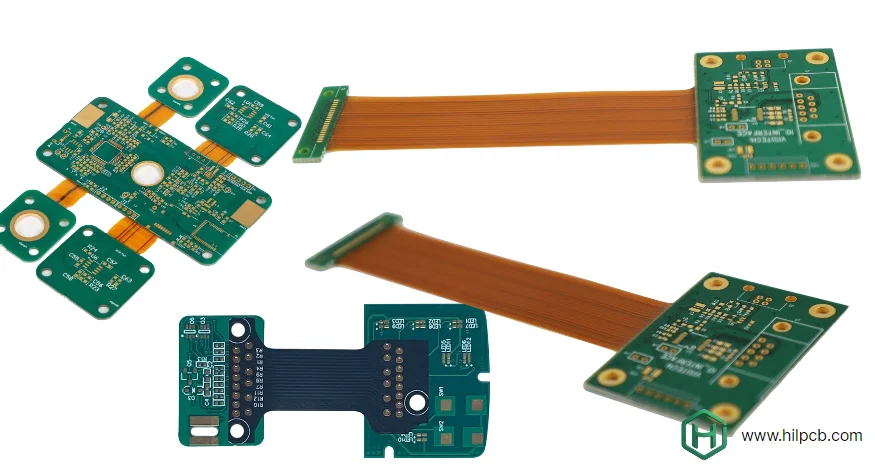
Quality Standards and Certifications
Medical, aerospace, and automotive applications demand verified manufacturing processes and complete traceability. Request current facility certificates and the applicable production-site scope for any regulated industry program.
Quality-System and Acceptance Requirements to Agree:
- ISO 9001 quality-system certification where required, with the certificate edition, site, scope and validity verified
- Where applicable, an independently verified ISO 13485 quality system for the actual contracting manufacturing site
- IATF 16949 where applicable to the automotive supply-chain role and customer contract
- AS9100 where specified for the aerospace program, with site and operation scope verified
- IPC-A-610 workmanship criteria for assembled rigid-flex PCBAs, at the customer-specified class; IPC-6013 for bare flexible and rigid-flex circuit performance, using the contractually agreed revision
Material Traceability Define the traceability needed for laminates, polyimide films, adhesives, conductors and assembled components. Agree lot or serial linkage, test records, revision history and retention period. These records support investigation; they do not by themselves establish root cause, medical-device approval or airworthiness.
Testing and Validation In addition to agreed electrical acceptance, define application-specific qualification where required:
- Dynamic flex testing to specified cycle counts
- Temperature cycling using the specified range, dwell, ramp, cycle count and failure criteria
- Humidity exposure testing
- Mechanical stress analysis
- Impedance verification for high-speed PCB requirements
Bend and Transition Information for the RFQ
| Design input | What to specify | What to verify |
|---|---|---|
| Installation versus repeated flex | Formed drawing, minimum radius, bend direction and cycle requirement | Qualified construction and representative bend testing |
| Flex stackup | Polyimide, adhesive, copper and coverlay thicknesses | Finished flex thickness, conductor strain and material compatibility |
| Transition region | Rigid-edge geometry, component/via locations and strain relief | Clearance from the bend and assembly/mechanical interference |
| Stiffeners and attachment | Material, thickness, adhesive and placement | Connector support, keepouts and assembly temperature compatibility |
| Acceptance plan | Specification revision/class, continuity, impedance and qualification sampling | Reports linked to the released build and agreed use conditions |
Frequently Asked Questions - Rigid Flex PCB Manufacturing
What is the minimum order quantity for a rigid-flex PCB?
HILPCB has no minimum order quantity for rigid-flex PCBs and accepts single prototypes through production volumes of 100,000+ units. Panel utilization, construction and quotation still determine the practical order plan; customers commonly begin with 5–10 validation prototypes.
How much does rigid-flex PCB manufacturing cost?
Cost depends on rigid/flex layer count, flex area, material construction, panel utilization, via structure, testing and quantity. Recorded historical quotation ranges were 5-piece prototypes at $80–300 per design, 100–500-piece low-volume builds at $12–45 per unit, and production orders of 2,000+ pieces at $6–20 per unit. HILPCB often identified 20–30% savings through optimization in the recorded quotation context; savings depend on design, scope and volume and are not fixed for a new order. HILPCB quotes the submitted scope; compare identical fabrication and assembly requirements and agree any revalidation.
What are lead times for rigid-flex PCB manufacturing?
HILPCB’s stated rigid-flex lead-time options are 12–15 days for prototypes, 20–25 days for production, and 8–10 days for express prototypes. The quoted schedule depends on complexity, materials, quantity and approvals; confirm whether small batch assembly, component procurement and shipping are included.
What materials are used in rigid-flex PCB manufacturing?
Rigid sections may use FR-4, high-Tg, Rogers or another compatible laminate. Flexible sections commonly use polyimide-based copper laminates with adhesive or adhesiveless constructions. Specify the coverlay film and adhesive as a system rather than treating an adhesive alone as a coverlay. Stiffeners may be FR-4, polyimide or metal where the design supports them. Confirm compatibility with bending, lamination and assembly conditions.