
Rigid-Flex PCB Manufacturer | Fast-Turn Prototyping & Scaled Production
Direct factory rigid-flex PCB manufacturer delivering high-density 3D electronic integration from 24–48h fast-turn prototypes to volume production. As a trusted rigid flex pcb supplier, HilPCB manufactures advanced rigid flex board and rigid flex circuit boards that eliminate bulky wire harnesses and cut total assembly costs by up to 25% to 35%.
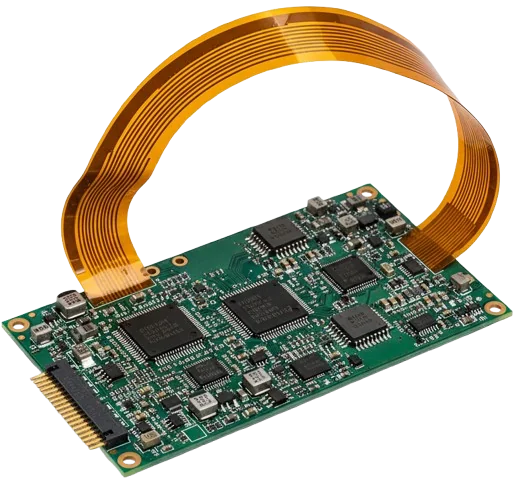
Integrating Form and Function for Advanced Electronics
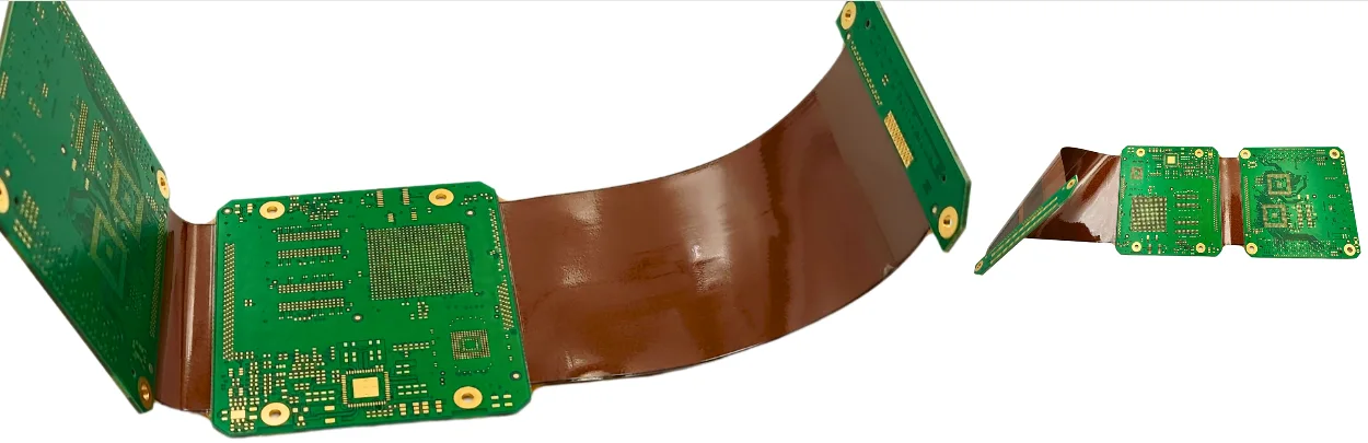
Eliminate connectors and cables; improve SI and reliabilityRigid-flex PCBs combine flex PCB and FR-4 technology to eliminate fragile interconnects and enable compact 3D architectures. By removing board-to-board connectors—common failure points—systems gain reduced weight, fewer assembly steps and tighter signal-integrity margins. Typical builds deliver assembly cost savings of 15–25% and enhanced long-term reliability compared with traditional rigid + cable harness designs.
We optimize bend radius, copper balancing and coverlay window geometry to minimize strain at rigid-to-flex transitions. For high-density BGAs, we integrate HDI microvias and via-in-pad structures to preserve routing channels while keeping flex areas stress-free. See our IPC Class 3 workmanship guide for aerospace and medical acceptance criteria.
Critical Risk: Excessive copper thickness or asymmetric stackup at the rigid-flex junction can cause layer delamination, cracked vias or conductor fatigue after dynamic bending. Improper adhesive flow or mismatched CTE (coefficient of thermal expansion) between PI and FR-4 leads to Z-axis warpage and open circuits under thermal cycling.
Our Solution: We perform DFM reviews with FEA bend-simulation to verify strain < 0.3% across the flex region. Staggered trace routing, teardrops and coverlay fillets relieve stress; minimum bend radius follows R ≥ 10× t (ten times the material thickness). Controlled lamination under lamination process control and post-cure ensures adhesive uniformity and peel strength. For high-speed differential pairs, impedance tuning per impedance-control guide maintains 90 Ω ± 5% continuity across flex transitions.
For ultra-reliable dynamic applications—foldable devices, avionics harnesses, and wearable electronics—rigid-flex architectures can be combined with High-Tg PCBs for superior thermal endurance or ceramic PCB interposers for hybrid mechanical support. Learn more in our signal-integrity design and flex-assembly tutorials.
- Connector and harness elimination for higher reliability
- 3D packaging freedom with reduced volume and weight
- Improved signal integrity from shorter interconnects
- Static and dynamic bend options with tuned stackups
- Natural handoff to turnkey box build
🚀 Quick Quote Request
📋 Get Full Capabilities
Precision Manufacturing for Complex Rigid-Flex Designs
Specialized lamination, laser microvias, controlled-depth routingRigid-flex fabrication requires bonding dissimilar materials (FR-4 and polyimide) without entrapment or delamination. We use staged-pressure vacuum lamination with bondply and coverlay control; polyimide cores are prepared with plasma for adhesion while preserving Ra smoothness. UV-laser drills form microvias down to 75–100 μm with depth control ±5 μm. Controlled-depth routing precisely exposes flex areas from rigid panels.
Quality gates include dynamic bend tests (thousands to millions of cycles), thermal shock −40↔+125 °C, and microsections of transition zones. Learn more in our thermal shock testing overview and PCB manufacturing guide.
- Specialized lamination for FR-4/PI stacks
- Laser drilling/ablation for high-precision features
- Controlled-depth routing in transition windows
- Dynamic bend and thermal shock validation
- Full turnkey SMT + system integration available
Rigid-Flex Technical Specifications
Engineered for demanding aerospace, medical and automotive applications
| Parameter | Standard Capability | Advanced Capability | Standard |
|---|---|---|---|
Layer Count | 2–12 layers total (rigid 2–20; flex 1–8) | Up to 30+ layers (rigid ≥30; flex ≥8) | IPC-6013 |
Base Materials | FR-4 Tg 150–170 °C, Polyimide (PI) | High-Tg FR-4, LCP, adhesiveless PI, low-loss laminates | IPC-4101/4204 |
Board Thickness | 0.4–3.2 mm | 0.2 mm flex to 5.0 mm rigid | IPC-A-600 |
Copper Weight | 0.5–2 oz (17–70 μm) | Up to 6 oz (rigid sections) | IPC-4562 |
Min Trace/Space | 75/75 μm (3/3 mil) | 50/50 μm (2/2 mil) | IPC-2223 |
Min Hole Size | 0.15 mm (6 mil) mechanical | 0.075 mm (3 mil) laser microvia | IPC-2222 |
Stiffener Materials | Polyimide, FR-4 | Stainless steel, aluminum | Design specific |
Min Bend Radius | 10× flex thickness (dynamic) | 6× flex thickness (static; 1–2 layers) | IPC-2223 |
Impedance Control | ±10% | ±5% with TDR | IPC-2141 |
Surface Finish | ENIG, OSP, Immersion Silver | ENEPIG, Hard/Soft Gold | IPC-4552/4556 |
Quality Testing | E-test, AOI, dimensional checks | Dynamic flex testing, TDR, thermal cycling/shock | IPC-9252 |
Certifications | ISO 9001, UL, RoHS/REACH | AS9100, ISO 13485, IATF 16949 | Industry standards |
Lead Time | 7–15 days | ≈5 days quick-turn | Production schedule |
Need capabilities beyond this product? Explore our full manufacturing capabilities
Ready to start your PCB project?
Whether you need simple prototypes or complex production runs, our advanced manufacturing capabilities ensure excellent quality and reliability. Get your quote within 30 minutes.
Critical Rigid-Flex Design Considerations
Keep copper features perpendicular to bend lines, avoid vias and pads in dynamic flex areas, and offset traces between layers to distribute strain. Use staggered or bookbinder layer lengths for multilayer flex to prevent inner-radius compression. Observe minimum radius rules (e.g., 10× flex thickness for dynamic) and add anti-pad/relief features near transitions. For fundamentals, see IPC 2221/2223 design notes and our flex PCB page.
Need Expert Design Review?
Our engineering team provides free DFM analysis and optimization recommendations
Specialized Rigid-Flex Process Flow
Typical flow: flex core imaging → coverlay/bondply prep → inner-layer AOI → staged lamination with rigid cores → laser microvia and controlled-depth routing → finish and final inspection. Registration is verified at each stage; plasma desmear cleans PI holes; X-ray confirms via targets. Reference our manufacturing guide for step-by-step controls.
Rigid Flex PCB Assembly: Impedance Control, Depth Routing and Hybrid Construction
Rigid flex PCB assembly is the stage where most rigid-flex programs reveal problems that were invisible at the fabrication stage: a flex tail that will not survive the reflow fixture, a stiffener that collides with a connector, or an impedance target that was met during fabrication but not through the assembly transition.
Assembly handling of flex regions. Flexible sections must be supported during printing, placement and reflow, and the support method must not compress the bend area. Panel design, carrier fixtures and depanelisation sequence all affect the outcome. Because rigid-flex panels are expensive, the assembly plan should be agreed alongside the stackup rather than after the boards arrive.
Impedance control across transitions. Rigid-flex impedance control is harder than on a rigid board because the dielectric system and reference planes change as a signal moves from the rigid section into the flex section. The transition must be modelled as part of the channel. Where impedance matters, define coupon structures on both the rigid and flex regions so the result can be verified after assembly, not inferred.
Depth-controlled routing. Depth-controlled rigid-flex construction uses controlled-depth milling to expose inner layers or create cavities without cutting through the flexible core. This enables access to buried features and supports component-in-cavity designs, but the tolerance on remaining material is tight and must be qualified per stackup. A custom depth-controlled board needs the target depth, tolerance and acceptance method stated on the fabrication drawing.
Hybrid and camera-module applications. A hybrid rigid-flex PCB combines rigid laminates with flexible sections and sometimes mixed dielectrics, which is common as camera-module designs pack a sensor, driver and connector into a folding assembly. Those builds stress both registration and bend-radius discipline, so early DFM review is the cheapest control available. For assemblies that also route high-speed signals, coordinate with high-speed PCB design rules and refer to flex PCB guidance for the flexible sections.
When the bend axis and the rigid-to-flex transition are defined, send the drawing through the rigid-flex engineering review so the stackup, depth-control tolerance and assembly fixture are agreed before the first panel is built.
Materials & Stackup Optimization
Choose adhesiveless PI for dynamic flex (better ductility), adhesive-based PI for cost-sensitive static bends, and high-Tg FR-4 for thermal margin. For RF or ultra-low loss, consider LCP or low-loss cores. Add PI/FR-4 stiffeners under components in flex areas to prevent solder-joint fatigue during SMT. For high-speed routing from rigid to flex, coordinate with our high-speed PCB team.
Quality & Reliability Validation
We apply AOI, flying-probe/E-test, microsections of flex-rigid transitions, dynamic bend fatigue, and thermal shock −40↔+125 °C. Impedance coupons verify ±5% tolerance when specified. Full MES traceability links material lots, process parameters and test data—see thermal shock testing for methodology.
Rigid-Flex Standards and Design Verification: IPC-6013 and Bend-Area Discipline
Rigid-flex is governed by its own qualification standard, and knowing which clauses your program must satisfy changes both the stackup and the evidence package that should ship with the lot.
Standards that apply. IPC-6013 (current revision IPC-6013E) covers qualification and performance of flexible and rigid-flex printed boards, including the specific requirements for flexible base materials, coverlay adhesion and bend capability. Where a program also carries aerospace or medical requirements, those add class and documentation expectations on top rather than replacing 6013. State the class explicitly on the purchase order, because acceptance criteria differ materially between them.
Bend-area design discipline. The rules that most affect yield are geometric. Copper should run perpendicular to the bend line where possible, with plated through-holes excluded from the bend area. Coverlay edges must be offset from the bend, and the neutral axis of the stack should place the conductor in the least-stressed layer. Specifying the bend radius as a ratio of stack thickness, rather than as an absolute dimension, keeps the requirement unambiguous across revisions.
Verification that proves the design. Rigid sections and their flex joints should be verified by microsection of the transition zone and by bend or flex-to-install testing that represents the actual assembly motion. A design that passes a static bend check may still fail a repeated-flex requirement, and the difference only appears if the test is defined with the requirement.
Mechanical interfaces. Where a rigid-flex part must also provide the interconnect between two rigid PCB assemblies, define the mechanical datums and the strain relief at both ends. Those interfaces are typically where field failures originate. Review flex PCB material guidance when the flexible section dominates the design.
Applications & System-Level Integration
Aerospace/Defense: avionics, gimbals, payloads.
Medical: implantables and imaging under ISO 13485 controls.
Automotive: camera/sensor modules and lighting—see automotive PCB. For enclosure, labeling and fulfillment, hand off to box build services.
Engineering Assurance & Certifications
Experience: connector-less architectures with validated bend life; Expertise: coverlay windowing, bookbinder stacks, laser microvias, and controlled-depth routing; Authoritativeness: IPC-6013 Class 3 documentation and audits; Trustworthiness: MES traceability from lot to unit level with reports on AOI/E-test/microsections and mechanical cycling.
- Controls: lamination windows, PI plasma, microvia depth, routing depth
- Traceability: digital traveler with lot certificates
- Validation: dynamic bend, thermal shock/cycle, TDR coupons
Frequently Asked Questions
When should I choose rigid-flex over rigid boards with cables?
What is a bookbinder construction and when is it used?
How do you set minimum bend radius?
Can components be mounted on flex sections?
Do you support high-speed controlled impedance in rigid-flex?
Which standard applies to rigid-flex boards?
Experience Advanced PCB Manufacturing Excellence
From simple prototypes to complex production runs, our world-class factory delivers superior quality, fast turnaround and competitive pricing. Join thousands of satisfied customers who trust us with their PCB manufacturing needs.