

Planning Your First Circuit Board Project
Before you open any PCB design software, you must clearly define what your project is supposed to achieve. Your planning stage determines the difficulty, cost, and manufacturability of the entire board.
Define what problem your first PCB is solving
Create a simple project brief including:
- Functional goals
- Performance requirements (voltage, current, signal speed)
- Environmental conditions (temperature, vibration, enclosure)
- Mechanical constraints (maximum size, connector positions, height limits)
This short document will guide every technical choice—layer count, material, routing, connectors, and even which PCB manufacturer is suitable.
Determine how many boards you need
- Prototypes: 5–10 pieces
- Engineering validation: 10–20 pieces
- Pre-production: 50+ pieces
If your collaborators are in multiple countries, produce enough boards so all teams can test simultaneously.
Choosing PCB Technology and Stackup for Your First Circuit Board
Your PCB technology choice converts an idea into an actual physical product. For a first circuit board, the goal is to use the simplest technology that meets requirements while staying cost-efficient.
Standard rigid FR4 for first-time designers
For most control boards, sensor modules, or general electronics, traditional FR4 is the ideal starting point. Refer to common structures used in FR4 PCB manufacturing.
If your signals are low-speed and routing is moderate, a 2-layer PCB is enough. When complexity increases, a 4-layer PCB dramatically improves EMC, routing density, and power integrity. These belong to standard multilayer PCB manufacturing processes.
A classic 4-layer stackup:
- L1 – Signal
- L2 – Ground
- L3 – Power + slow signals
- L4 – Signal
This is the most beginner-friendly controlled-impedance structure.
High-speed and high-frequency versions of your first PCB
If your board includes USB 3.x, Ethernet, HDMI, or LVDS interfaces, you need:
- Controlled impedance
- Stable dielectric thickness
- Continuous reference planes
- Careful routing constraints
Such boards follow principles similar to high-speed PCB manufacturing.
If your circuit carries RF modules (BLE, WiFi, sub-GHz), you are entering the domain of high-frequency PCBs. For a first project, use RF sections only when necessary, because material selection becomes more involved.
Flex and rigid-flex options for small enclosures
If your PCB must fold into small device cavities or replace wiring harnesses, you may need:
- Flexible polyimide sections
- Hybrid rigid + flex zones
These belong to flex PCB manufacturing or rigid-flex PCB manufacturing.
But for a first circuit board, start with rigid FR4 unless mechanical constraints strictly require flex materials. Later versions can upgrade as the product matures.
High-temperature or high-reliability needs
If your board will operate inside vehicle compartments, industrial heaters, or frequent reflow cycles, choose high-temperature materials such as high-TG PCB laminates.
These maintain dimensional stability and reliability under harsh environments.
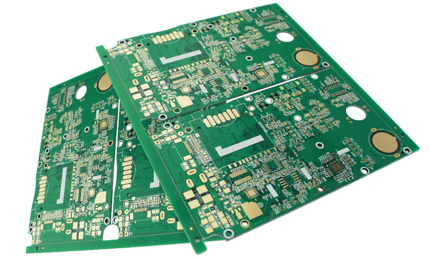
Schematic, Layout, and DFM Workflow for Your First Circuit Board
Regardless of where your PCB is manufactured, your design flow determines whether the project will succeed or fail.
Start with a clean, structured schematic
Good habits include:
- Clear power tree showing all rails and current consumption
- Decoupling capacitors placed directly next to IC supply pins
- Identifiable net names (USB_DP, ETH_TX+, ADC_IN1, etc.)
- Separation of digital, analog, RF, and power domains
- Test ports planned from day one
This avoids layout confusion and reduces iteration cycles.
Layout workflow: from blocks to details
Divide the PCB into functional regions:
- Power supply area
- MCU/processor section
- Sensor or RF region
- Connectors and interfaces
- Motor drivers or high-current components (if any)
Place components logically within each block. If using BGAs or high-pin-count ICs, apply the same discipline used in HDI PCB design, even if your first board does not use microvias yet. This builds long-term design skills.
Routing strategy for first-time designers
Follow this routing order:
- High-speed differential pairs
- Clock and timing lines
- Power distribution
- Sensitive analog signals
- Remaining digital signals
- LEDs, buttons, low-priority I/O
Always check:
- Shortest possible return paths
- Avoiding splits in grounding
- Limiting via count on impedance-controlled nets
- Maintaining symmetry on differential pairs
DRC and DFM checks
Before generating Gerber files:
- Run DRC with your manufacturer’s actual capabilities
- Verify drill sizes, annular rings, solder mask clearance
- Ensure text does not overlap pads
- Maintain adequate copper-to-edge spacing
- Add panelization marks only if required
This step often saves more time than any other.
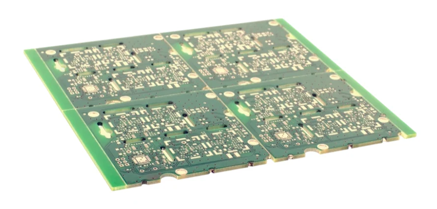
Preparing Files and Working With Overseas PCB Manufacturers
If this is your first time ordering a circuit board from an overseas manufacturer, the process may feel unfamiliar — especially when working with factories in Asia. Here's how to prepare your files correctly.
What files overseas factories expect
Include these in your final package:
- Gerber files (RS-274X or X2)
- NC drill files
- Stackup diagrams or layer notes
- Board outline with cutouts
- Surface finish requirements
- Copper thickness specification
- Impedance requirements (if applicable)
- Fabrication notes
- Pick-and-place file (for assembly)
- BOM with manufacturer part numbers
These are universally recognized across global PCB suppliers.
Communicating with international manufacturing teams
Tell the factory:
- It is your first circuit board — you would like DFM guidance
- Whether cost, quality, or lead time is your top priority
- Whether this prototype will scale into future mass production
- If you need stencil files or full turnkey assembly later
If long backplanes, modular boards, or distributed architectures are in your roadmap, these skills easily extend to backplane PCB manufacturing.
Assembly Strategy for Your First Circuit Board
A PCB is only complete when it is assembled and working. For beginners, a hybrid assembly approach is usually best.
Soldering your first prototypes
Hand-soldering is acceptable for:
- 0603/0805 passives
- SOIC/QFP ICs
- Connectors and headers
- Modules with accessible castellated edges
But if your design includes QFN, BGA, or dense fine-pitch parts, it is better to use professional SMT assembly services.
Through-hole and mixed assembly
Large connectors, relays, and transformers require through-hole assembly processes, such as:
- Manual soldering
- Wave soldering
- Selective soldering
For first-time designers, follow these rules:
- Reserve enough soldering space
- Avoid tiny pads buried inside large copper pours
- Use thermal reliefs to prevent heat sinking
- Add mechanical support for large connectors
Once your product stabilizes, you can move to turnkey PCB assembly, where fabrication, component sourcing, and assembly are done by one partner.
Testing, Debugging, and Iterating on Your First Circuit Board
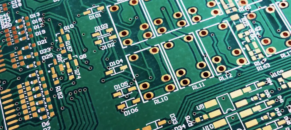
Your first board may not work perfectly. That is normal. Testing and iteration are part of professional hardware development.
Plan for testability during design
Include:
- Test pads for critical voltage rails
- UART/JTAG/SWD connectors
- Probe points for clocks and differential pairs
- Jumpers to isolate subsystems
A board that is easy to probe is much easier to debug.
Initial power-on sequence
- Check shorts between power rails and ground
- Power the board with a bench supply current limit enabled
- Measure all voltages
- Run minimal firmware to confirm life signs
- Test communication interfaces one by one
- Stress-test under load, temperature, and long runtime
Document everything, especially unexpected behavior.
Record lessons for future boards
Before starting your second design, review:
- DFM issues the factory reported
- Layout problems that caused noise or instability
- Thermal hotspots
- Mechanical issues with connectors
- Missing test points
- Components that were hard to solder
These notes will make your next PCB dramatically better.
Final Thoughts
Your first circuit board is more than just a prototype. It is the foundation of your long-term hardware design workflow. By choosing the right materials, following a structured design sequence, preparing proper manufacturing files, and working closely with local or overseas factories, you can build a board that works reliably—and creates a repeatable engineering process you will use for years.
If you need help with stackups, manufacturing options, DFM, or turnkey assembly for your first PCB, professional PCB manufacturers can guide you from early concept to mass-production readiness.
Common Questions
What should first-time PCB designers focus on first?
Start with the real electrical function, board size constraints, component choices, and how the product will be assembled and tested. A simple, well-prioritized first board usually succeeds more often than an ambitious layout with too many unknowns.
Why do stackup, material choice, and manufacturing capability matter so early?
They affect impedance control, thermal performance, mechanical strength, cost, and lead time from the beginning. If you ignore them until the layout is finished, you may have to redo routing, footprints, or even the entire board concept.
Why should DFM and testability be planned before fabrication?
Because a board that is hard to build or hard to probe will cost more time and money even if the schematic is correct. Adding test points, assembly clearances, and fabrication-friendly rules early prevents avoidable problems during prototype bring-up.
Why is it helpful to work with the manufacturer early on a first board?
An experienced PCB or PCBA supplier can flag risks in stackup, drill sizes, copper balance, panelization, and assembly before files are released. That feedback improves the odds that your first revision will power up and move to the next stage faster.